Light-Emitting Planar Body-Structured Body

a planar body and light-emitting technology, applied in the field of can solve the problems of large restriction of self-luminous type light-emitting planar body structure using black light, inability to appraise design, etc., and achieve the effect of expanding the area

Inactive Publication Date: 2007-12-27
DOPPEL
View PDF0 Cites 150 Cited by
  • Summary
  • Abstract
  • Description
  • Claims
  • Application Information

AI Technical Summary

Benefits of technology

[0015] In the invention of the application, as described above, because an LED (light-emitting diode) which radiates ultraviolet radiation or near ultraviolet radiation is used as the light source, and because the light-emitting planar body is a molding made of light-transmitting resin containing dispersed therein at least one type of phosphors and light-storing bodies together with ligh...

Problems solved by technology

However, in case of using such an external illumination system, the presence of the black light used as the light source is visible, and because of the limitations concerning the arrangement of the black light, the application of the light-emitting body has been considerably restricted.
Furthermore, in the case of self-luminous type, the design was not appraisable because the base material of the light-emitting planar body was transparent and the presence of the black light provided at the back of the light-emitting planar body was externally visualized.
Due to these reasons, the application of self-luminous type light-emitting planar body structures using black light was gr...

Method used


Image

  • Light-Emitting Planar Body-Structured Body
  • Light-Emitting Planar Body-Structured Body
  • Light-Emitting Planar Body-Structured Body

Examples


example 1

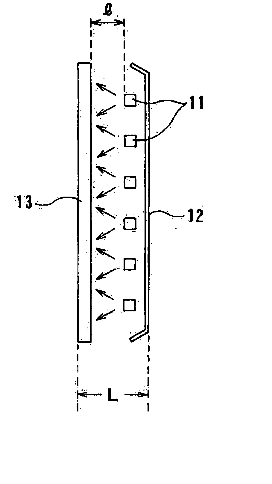
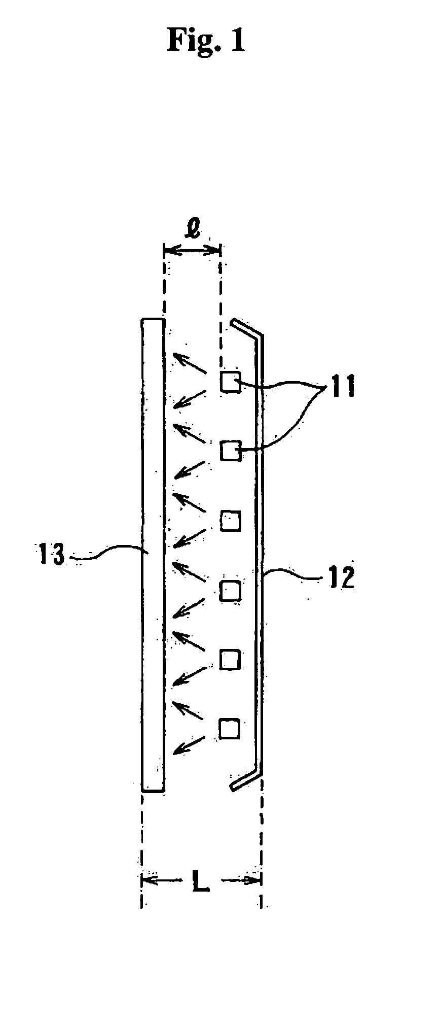
[0071] Two types of phosphorescent light-emitting planar body (3.0 mm in thickness), whose composition is shown in Table 1, were prepared, and were set in a zigzag arrangement as shown in FIG. 2 by using a diffusion type ultraviolet-emitting LED (NICHIA CORPORATION, NSHU:550: 5-mm diameter, light output 700 μW, diffusion angle 100°). In the arrangement, m=60 mm and l=30 mm. A reflector plate was used to give a total thickness of L=50 mm. The LED light source was not perceived at all from the front side of the light-emitting planar body.

[0072] Uniform light emission was obtained for both phosphorescent red light-emitting planar body and phosphorescent blue light-emitting planar body with excellent vision properties.

[0073] Luminance of red: 7 cd / m2 and blue: 7 cd / m2 was obtained.

TABLE 1Amount blended (W %)PhosphorescentPhosphorescentblue light-red light-emittingemittingplanar bodyplanar bodyMMA18.00%19.00%Peroxide-based hardening material 0.40% 0.40%Transparent small particle58.00...

example 2

[0074] Light-storing light-emitting planar body (4.0 mm in thickness), whose composition is shown in Table 2, was prepared, and was set in a zigzag arrangement as shown in FIG. 2 by using the same light source as that used in Example 1. In the arrangement, m=50 mm and l=25 mm. No reflector plate was used. The total thickness L=45 mm.

[0075] Similar to Example 1, the LED light source was not perceived at all from the front side of the light-emitting planar body.

[0076] After irradiation for 60 minutes, the light source was switched off, and the time elapsed to yield a luminance of 3 mcd / m2 was measured. The time thus obtained was 8.5 hours.

TABLE 2Amount blended(W %)Light-storing (green)light-emittingplanar bodyMMA18.00%Peroxide-based hardening material 0.40%Transparent small particle components (quartz)56.00%Fine particle components (aluminum hydroxide)17.00%Light-storing pigment (NEMOTO & CO., LTD.) 8.60%Total  100%

example 3

[0077] A structure body shown in FIG. 3 was prepared. The light-emitting planar body (13) with the composition shown in Table 1 in Example 1 was prepared at a thickness of 3 mm, and a light-transmitting resin molding (14) having embedded therein a 30 mm thick LED (11) light source was placed in contact with the back plane of the light-emitting planar body.

[0078] A diffusion type ultraviolet-emitting LED (NICHIA CORPORATION, NSHU:550: 5-mm diameter, light output 700 μW, diffusion angle 100°) was used as the LED (11) light source, and was buried in the resin molding (14) obtained by shaping transparent acrylic resin in such a longitudinal arrangement as that shown in FIG. 3 and a planar arrangement shown in FIG. 2, with m=30 mm.

[0079] On switching on the LED (11) light source, the presence of the LED (11) was not visible from the front side of the light-emitting planar body (13). Uniform light emission was obtained for both phosphorescent red light-emitting planar body and phosphore...


PUM


Abstract

A light-emitting planar body-structured body characterized in that it comprises an LED (light-emitting diode) light source which radiates ultraviolet radiation or near ultraviolet radiation and a planar body provided disposed in front thereof, and that the planar body is a light-transmitting resin molding containing dispersed therein at least one type of phosphors and light-storing bodies together with light-transmitting inorganic particles.

Description

TECHNICAL FIELD [0001] The invention of this application relates to a light-emitting planar body-structured body. In further detail, the invention of the application relates to a thin-type novel light-emitting planar body-structured body, which utilizes a self-luminous system using ultra-violet emitting light source, whose light source is not visible from the outside and which is capable of efficiently emitting planar light, and which is yet capable of emitting light even after stopping light irradiation from the light source. BACKGROUND ART [0002] There have been known heretofore light-emitting planar body structures which provide planar light emission from light-emitting bodies or light-storing bodies that are incorporated in transparent bodies made of resins, glasses, etc., by irradiating ultraviolet radiation using a phosphorescent light which emits ultraviolet radiation (black light), and they have been applied to various types of signs, advertisement panels, guiding plates, et...

Claims


Application Information

Patent Timeline
IPC IPC(8): G02B27/00G09F13/04H01L33/00H01L33/50H01L33/60
CPCF21W2111/00H05B33/18G09F13/04F21Y2101/02F21Y2115/10
Inventor SAKAI, MIEKOSHINOMIYA, KENICHIROSAITO, KENICHIROINOUE, YUKIHIKO
Owner DOPPEL
Why Eureka
Try Eureka