Vascularized tissue graft

a vascularized tissue and graft technology, applied in the field of tissue engineering, can solve the problems of limited technique, limited vascularized tissue production, and inability to produce other vascularized tissues suitable for grafting, and achieve the effects of facilitating delivery, repairing tissue deficit, and augmenting inappropriately depleted tissu

Inactive Publication Date: 2007-12-27
VICTORIAN TISSUE ENG CENT
View PDF4 Cites 54 Cited by
  • Summary
  • Abstract
  • Description
  • Claims
  • Application Information

AI Technical Summary

Benefits of technology

[0025] The ability to repair a tissue deficit and / or augment inappropriately depleted tissue using the method of the present invention provides the further possibility of facilitating the delivery of one or more desirable gene product(s) to a subject. Cells and / or developing tissue within or on the support matrix may be transformed with an appropriate genetic construct comprising the desired gene prior to being transplanted into the recipient.

Problems solved by technology

One of the major challenges faced in tissue engineering is to create differentiated tissue of the appropriate size and shape.
Tissue created without a functional vasculature is strictly limited in size by the constraints of oxygen diffusion; if the tissue is too large it will become necrotic before the host has time to create a new blood vessel supply.
Because these flaps must retain their blood supply to remain viable after transplantation, the origin of the flaps is limited to those areas where there is an anatomically recognized blood vessel source.
This technique is, however, limited by the availability of donor tissue, and the disfigurement that results at the donor site.
However, while the generation of vascularized skin using an AV loop has been demonstrated, the production of other vascularized tissues suitable for grafting remains elusive.
Vascularized adipose tissue, for example, is often demanded in reconstructive procedures; however, donor mature adipose tissue is extremely fragile, and will rapidly become necrotic if not immediately reconnected to a functional blood supply.
Furthermore, the use of conventional autologous transplantation techniques involves “robbing Peter to pay Paul”, producing disfigurement at the donor site.

Method used


Image

  • Vascularized tissue graft
  • Vascularized tissue graft
  • Vascularized tissue graft

Examples


example 1

Preparation of Support Matrix

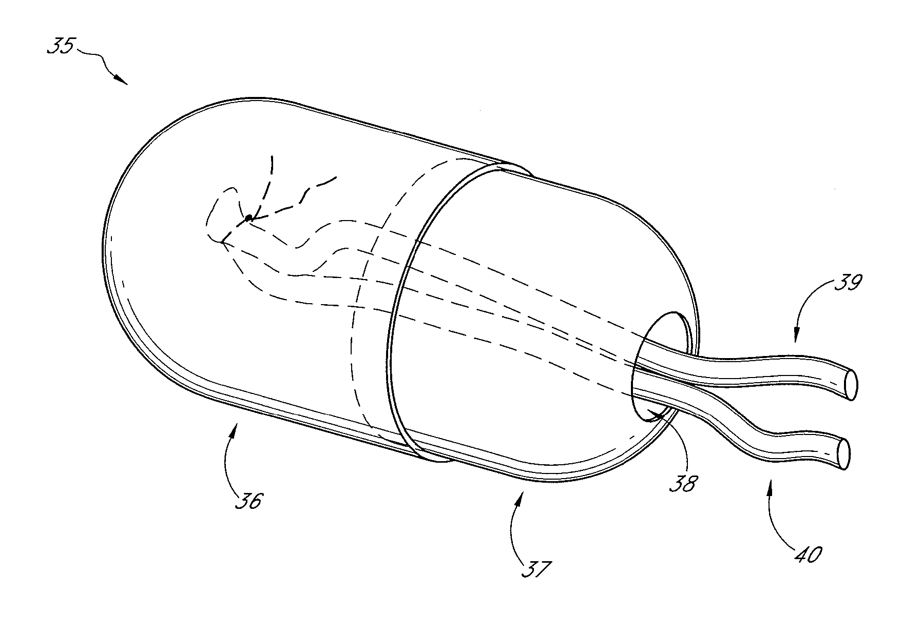
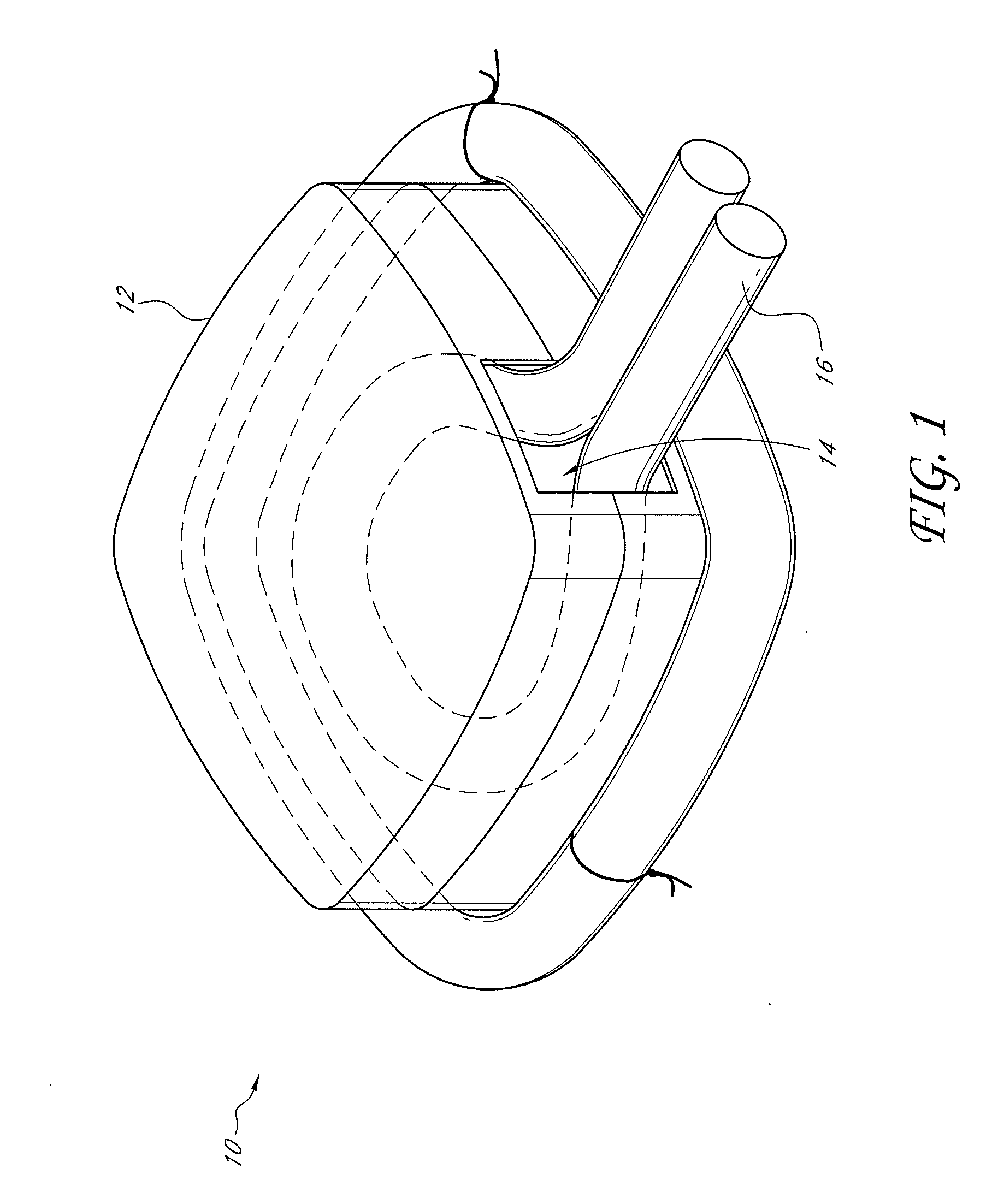
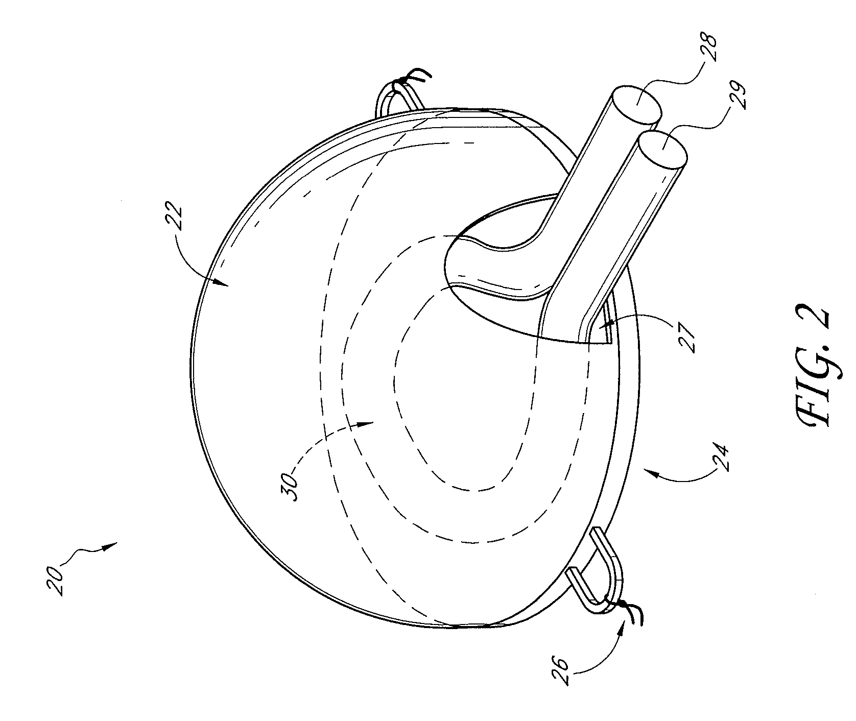
[0102] A custom-made polycarbonate chamber is prepared. It comprises a top and a bottom, and when the two halves are sealed together the internal volume is 0.45-0.50 mL. The general construction of the chamber 10 is illustrated in FIG. 1. In this exemplary chamber, the chamber is a transparent plastic cylindrical chamber with lid 12.

[0103] The basic chamber for use in rats is made of polycarbonate. In one variant, the chamber is made of polylactic acid or PLGA. The chamber is in the shape of a cylinder of external dimensions 14 mm diameter and 4 mm high, with a saw cut on one side to create an opening for the blood vessel entry and exit. Another variant has cut openings on opposite sides of the chamber to allow blood vessels to flow in one side and out the other. The chamber has a base and a removable lid 12. The base has holes to allow anchoring of the chamber to subcutaneous tissue. The internal volume is approximately 0.45-0.50 mL. The internal volu...

example 2

Creation of an AV Shunt Loop Inside the Tissue Chamber

[0114] The basic model has been described by Tanaka et al., 1996, supra. Briefly, male Sprague-Dawley rats (225-285 g) are anaesthetized with intraperitoneal phenobarbitone (50 mg / kg; 2.5 mL of a 6 mg / mL solution). Under sterile conditions an inferior-based flap is created in the right groin to expose the femoral vessels from the inguinal ligament to the superficial epigastric branch. A longitudinal incision was made in the left groin to harvest the left femoral vein from inguinal ligament to the superficial epigastric branch. This vein graft (approximately 1.5-3 cm long; usually 2 cm) was interposed between the recipient right femoral vein and artery at the level of the superficial epigastric artery by microsurgical techniques using 10-0 sutures. The shunt is placed into the chamber, the lid closed and the construct sutured to the groin musculature with the aid of small holes on the base of the chamber. An adipose layer was pla...

example 3

Assessment of Vascularization and Tissue Creation

[0116] At the specified time of exploration, the chamber is opened and the vessels cleaned and tested for patency. The vessels are tied off with a 5-0 silk suture at the entrance of the chamber and the flap harvested. In two of the five rats in each group, the flap is perfused via the aorta with India ink prior to harvest (details below). The flaps are assessed for volume and weight and placed in buffered 10% v / v formal saline (BFS) for histological examination. The animals are sacrificed with an intracardiac dose of sodium pentabarbitone (˜3 ml of 250 mg / m: solution) at the completion of the exploration.


PUM

PropertyMeasurementUnit
diameteraaaaaaaaaa
diameteraaaaaaaaaa
internal volumeaaaaaaaaaa

Abstract

The present invention relates generally to improved methods for tissue engineering including tissue transplantation, augmentation and regeneration. More particularly, the present invention provides a method for the generation of donor vascularized tissue suitable for use in tissue transplantation, augmentation and / or repair. The present invention further enables the use of a support matrix in the generation of an anatomical construct comprising the donor vascular tissue. The support matrix may be devised such that it has dimensions of a size and shape adapted to simulate those of tissue to be transplanted, augmented and / or repaired. In addition to its use in tissue repair, the methods and support matrix of the present invention may also find application as a means for delivering a desirable gene product to a subject. The method and support matrix of the present invention is conveniently be made available in the form of a kit, for use generally in the field of tissue engineering.

Description

RELATED APPLICATIONS [0001] The present application is a continuation of U.S. application Ser. No. 10 / 888,436, filed Jul. 8, 2004, which is a continuation-in-part of U.S. application Ser. No. 10 / 362,243, filed Sep. 22, 2003, which is the U.S. national phase under 35 U.S.C. § 371 of International Application No. PCT / AU01 / 01031, filed Aug. 21, 2001, which claims priority under 35 U.S.C. § 119(e) to U.S. Provisional Application No. 60 / 252,497, filed Nov. 22, 2000, all of which are incorporated herein in their entireties.BACKGROUND OF THE INVENTION [0002] 1. Field of the Invention [0003] The present invention relates generally to improved methods for tissue engineering including tissue transplantation, augmentation and regeneration. More particularly, the present invention provides a method for the generation of donor vascularized tissue suitable for use in tissue transplantation, augmentation and / or repair. The present invention further enables the use of a support matrix in the genera...

Claims


Application Information

Patent Timeline
Patent Type & Authority Applications(United States)
IPC IPC(8): A61F2/06A01N1/00C12M3/00A61K35/12A61K35/44C12N5/00C12N5/077
CPCA61F2/062C12M21/08C12M25/14C12M29/04C12M29/10A61K35/44C12N5/0653C12N2510/00C12N2533/30C12N2533/40C12N2533/90C12N5/0062
Inventor MORRISON, WAYNE A.MESSINA, AURORAKNIGHT, KENNETH R.PENNINGTON, ANTHONY J.
Owner VICTORIAN TISSUE ENG CENT
Why Eureka
Try Eureka