Coating composition, article, and associated method
a coating composition and composition technology, applied in the manufacture/treatment of superconductor devices, superconductor devices, electrical devices, etc., can solve the problems of corroding/chemically attacking the substrate, the substrate holder and assembly, and the other exposed surfaces of the reactor
- Summary
- Abstract
- Description
- Claims
- Application Information
AI Technical Summary
Problems solved by technology
Method used
Image
Examples
example 1
Preparation and Test
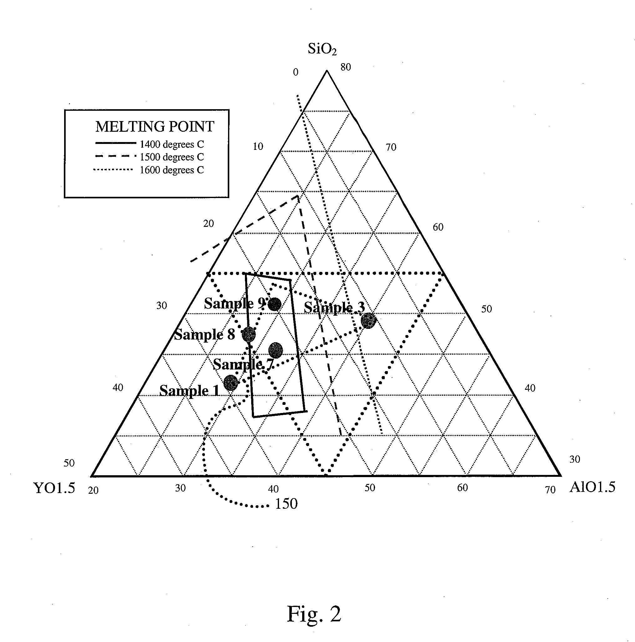
[0063]Samples 1-5 are prepared. Samples 1-5 include oxide powders mixed in the proportions set forth in Tables 1-2. The powders are weighed, mixed, and melted at temperatures greater than about 1500 degrees Celsius to achieve a fully molten homogeneous mass. The samples are allowed to cool slowly and then are tested.
TABLE 1Ingredients for Samples 1–5. Molar % of cations.Sample #YCeGdAlSitotal128.6——28.642.91002——28.628.642.9100312 ——40481004—12—40481005——12 4048100
TABLE 2Weight (g) of oxides used to meet molar ratios.Sample #Y2O3CeO2Gd2O3Al2O3SiO2total120——20601002——20206010038.1——2764.91004—15—25601005——8.12764.9100* Y = yttrium, Gd = gadolinium, Ce = cerium, Al = aluminum, Si = silicon (cation at %).
[0064]The glassy masses that result are cooled and tested. Samples 1-5 are each analyzed by two different tests: thermal mechanical analysis and reactive ion etch test. The samples 1-5 are then further tested for coefficient of thermal expansion values.
[0065]Therm...
example 2
Thermal Shock Tests
[0069]Two glass samples were cut and polished from a batch with a cation % composition of 23% Yttrium, 32% aluminum and 45% silicon. The dimensions were 30 mm×10 mm×2 mm and 23 mm×6 mm×2 mm. Three additional samples with dimensions 8 mm×8 mm×9 mm were cut using the same composition.
[0070]The two rectangular samples were placed in an alumina boat diameter=50 mm at room temperature, about 25° C. The alumina boat was then set onto ceramic blocks and placed in a preheated air furnace at temperature 800° C. The samples remained in the furnace for 30 minutes and then were removed and placed onto a ceramic block at room temperature. The test was repeated for the other three samples.
[0071]The two rectangular samples were ultrasonically inspected in a water tank using a 20 MHz F / 4 transducer. Signals were gated to produce an ultrasonic C-scan image. Differences in material properties will reflect incident ultrasound energy. Inclusions will appear at amplitudes higher than ...
example 3
Additional Material Compositions
[0073]Samples 11-20 are prepared by mixing oxide powders at the ratios listed in Table 7. Half of each mixture is then sintered under pressure to form a sintered article, and the other half of each mixture is heated to melting and then poured into a ceramic mold and cooled.
TABLE 7Ratio of oxides used to meet molar ratios.Sample #Y2O3CeO2Gd2O3Al2O3SiO2total112010—20501001220—102050100131010—25551001410—10255510015 51015205010016 51510205010017—1020205010018—2010205010019—15—25601002045——2535100* Y = yttrium, Gd = gadolinium, Ce = cerium, Al = aluminum, Si = silicon (cation at %).
[0074]Each of the samples 11-24 part A (sintered) and part B (molten) are formed into test pucks. Each puck is transparent with little or no visibly noticeable haze. Test pucks 21-24 are exposed to flourine gas (nitrogen trifluoride feedstock) at a temperature of 400 degrees Celsius for 6 hours with a measured gravimetric etch rate of less than 1 A / min.
PUM
| Property | Measurement | Unit |
|---|---|---|
| Temperature | aaaaa | aaaaa |
| Temperature | aaaaa | aaaaa |
| Temperature | aaaaa | aaaaa |
Abstract
Description
Claims
Application Information
 - R&D
- Intellectual Property
- Life Sciences
- Materials
- Tech Scout
- Unparalleled Data Quality
- Higher Quality Content
- 60% Fewer Hallucinations
Browse by: Latest US Patents, China's latest patents, Technical Efficacy Thesaurus, Application Domain, Technology Topic, Popular Technical Reports.
© 2025 PatSnap. All rights reserved.Legal|Privacy policy|Modern Slavery Act Transparency Statement|Sitemap|About US| Contact US: help@patsnap.com


