Extended and fixed INTable simultaneously imaged calibration and correction methods and references for 3-D imaging devices

a 3-d imaging and calibration method technology, applied in the field of 3d volumetric medical imaging, can solve the problems of inefficient process, large quantity of quantitative measurements, and inability to accurately measure objects, so as to minimize patient movement, avoid image artifacts, and reduce the size of cross-sectional area

Active Publication Date: 2012-05-29
ARNOLD BEN A
View PDF42 Cites 36 Cited by
  • Summary
  • Abstract
  • Description
  • Claims
  • Application Information

AI Technical Summary

Benefits of technology

[0020]An aspect in accordance with the invention disclosed herein is a calibration and reference couch pad, patient support device or tabletop that contains a variety of reference sample materials and test targets. The samples and targets are permanently enclosed within the pad, device or tabletop at fixed locations and are scanned simultaneously with patient scans. The samples and targets are small in cross-sectional size and area which provides patient comfort minimizes patient movement and avoids image artifacts. The samples and targets are further manufactured with high reproducibility and homogeneity and of sufficient length or repeating placements to always be present in the image for all torso exams without operator effort or placement or alignment verification. Any scan on any body part and at any time can be post-analyzed for a variety of tissue and image quality measurements. Patient comfort and radiation dose are improved. Operator time and effort is reduced. Costs to patients or facilities for repeat or additional scans at a later date are also reduced.

Problems solved by technology

All of these imaging devices however have significant limitations for quantitative measurements because the relationship is not sufficiently accurate or defined.
Thus, the measured object size is frequently inaccurate and will vary from operator to operator and from scanner to scanner depending on the display conditions and scanner properties.
In addition, the process to set and adjust the window and level requires operator time and is currently very inefficient.
The base material and calibration samples were large and dense and increased the dose and image artifacts.
CT numbers fail to be truly quantitative for several reasons.
Measurement errors also result from organ motion artifacts, tissue heterogeneity (fat, muscle, blood mixtures in sub-voxel volumes), gantry wobble and vibrations of the x-ray source, escape of K x-rays in the detectors, reconstruction algorithm, electronic noise, local beam hardening, scattered radiation and structure artifacts (usually from the presence of larger bones, air volumes and table structures).
In addition, measurements will vary with patient size and body type which is poorly recognized.
Because of the finite detector element size, the x-ray tube focal spot size and geometry, source movement during scanning and image back projection reconstruction imperfections, the finite number of views and source and / or table movement, the reconstruction of objects is not exact resulting in edge blurring by the point spread function (PSF) and loss of accurate tissue density representations at edges of objects.
Misalignments cause variable results and failure to reproduce positioning on follow-up exams months or years later can reduce measurement precision.
With prior methods, any study without the phantom cannot then or later be analyzed.
These features are now known to cause beam hardening and scatter artifacts and cause streaks from the reference phantom itself.
The larger / dense phantom increases radiation dose to the patient and / or reduces image quality by adding noise and scatter.
Prior methods and phantoms create patient discomfort from the hard material and sharp edges as well as large size.
Patient discomfort often leads to patient motion during the scan creating additional errors.
The required large sample sizes and removal of the phantom between studies resulted in short phantoms.
This requires added time and radiation dose to the patient.
Prior methods have been limited primarily to bone density measurements using calcium equivalent phantom samples.
These methods, while providing the ability to correct for scanner imperfections in idealized conditions, are not necessarily representative of the imaging device when the patients are present and are not representative of the device at the time of specific clinical exams.
For all of these and additional reasons, current test phantoms and methods for image corrections have limitations because they have been applied without the patient present.

Method used


Image

  • Extended and fixed INTable simultaneously imaged calibration and correction methods and references for 3-D imaging devices
  • Extended and fixed INTable simultaneously imaged calibration and correction methods and references for 3-D imaging devices
  • Extended and fixed INTable simultaneously imaged calibration and correction methods and references for 3-D imaging devices

Examples


Embodiment Construction

[0039]An important determination of the present disclosure is that the energy X-ray attenuation response (slope of the regression calibration equation) can be measured independently from the intercept of the regression calibration equation (i.e., the bias component). An additional determination of this discloser is that the slope is relatively independent of the sample size and surrounding material. The hybrid calibration method in combination with the disclosed device and methods has been shown to be superior to the use of external phantoms only and particularly so when large and dense phantoms are used.

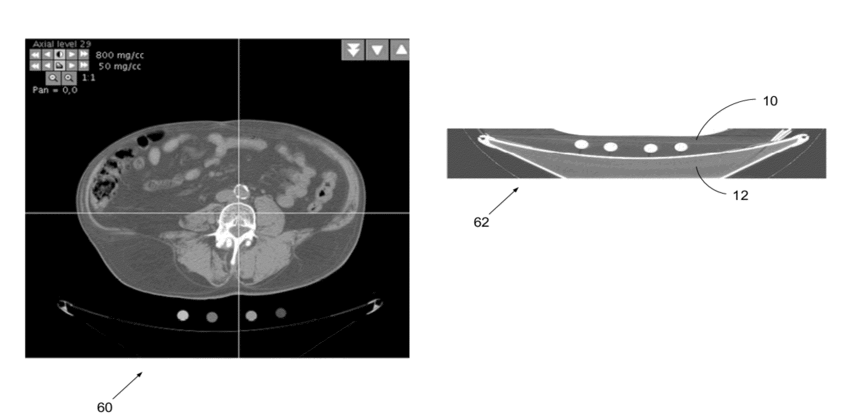
[0040]Another important determination of the present disclosure is that Z-axis integration of pixels in the small cross-sectional samples can be used preferably to phantoms with large samples and single slices. Practical use of the presently disclosed device incorporates innovative software methods which automatically detect and measure the small samples, which also may move somewha...


PUM


Abstract

Calibration and reference samples with reduced cross-sectional areas encased within imaging tables or couch pads have low attenuation properties and provide patient comfort. The samples are stable and provide reproducible images without artifacts. The torso-length samples avoid positioning errors and misalignment. Sample density or mass calibration materials include calcium compounds representative of bone and calcifications, iodine compounds for contrast angiography, gadolinium compounds for MRI, and fat and tissue equivalent materials. Density corrections for variable patient scatter and imperfect image reconstructions improve quantitative measurement. Automated computer methods detect the samples and record readings on all images over the extent of the scans without operator interaction. Spatial references function as location references and enable spatial correction of device imperfections such as point spread function (PSF) or motion for improved images. Comparative analysis of backward and forward projections corrects images based on simultaneous imaging of the references of known properties.

Description

RELATED APPLICATIONS[0001]The present application claims the benefit of priority under 35 USC §119(e) to U.S. Provisional Application No. 61 / 118,438, filed on Nov. 27, 2008.BACKGROUND OF THE INVENTION[0002]1. Field of the Invention[0003]The disclosure in the present application is in the field of 3-D volumetric medical imaging, and, in particular, is directed to an improved device and method to determine tissue properties in the body of a subject.[0004]2. Description of the Related Art[0005]Many diagnostic 3-D imaging devices are used in modem medicine for many types of exams, which are performed by subjective viewing of the images on either film or more commonly on electronic displays. This subjective viewing uses assumed quantitative image pixels, which define boundaries of tissues, organs or foreign masses, and discrimination of tissue types based on grey scale or color images, representative of the underlying tissue properties. Identification of diagnostic details is fundamental...

Claims


Application Information

Patent Timeline
Patent Type & Authority Patents(United States)
IPC IPC(8): G01D18/00
CPCA61B6/032A61B6/583A61B6/463A61B6/482A61B6/503A61B6/504A61B6/505
Inventor ARNOLD, BEN A.
Owner ARNOLD BEN A
Why Eureka
Try Eureka