Injector driver and drive method for the same

a technology of injectors and drivers, applied in the direction of fuel injection apparatus, electric control, charge feed system, etc., can solve the problems of increased apparatus cost, insufficient space and time for fuel to diffuse, and increased voltage applied, so as to suppress the variation in the valve-opening response time of the injector

Inactive Publication Date: 2008-01-24
TOYOTA JIDOSHA KK
View PDF4 Cites 12 Cited by
  • Summary
  • Abstract
  • Description
  • Claims
  • Application Information

AI Technical Summary

Benefits of technology

[0018]According to the above described injector driver and driving method thereof, because of generating a reference current signal that is synchronized to an injector valve signal for causing the injector to inject and that has a current increasing tendency substantially equivalent to an injector current waveform for the case in which a low voltage is applied to the injector; detecting the current that flows in the injector as a detected current signal; and controlling the elect...

Problems solved by technology

Also, there is not enough space and time for the fuel to diffuse after it is injected.
JP-A-11-351039, however, although there are the advantages of the valve opening response time (T0) of the injector being short and the fact that there is no influence from a variation in the battery voltage (+B), it is necessary to use a voltage boosting unit to increase the battery voltage, and necessary to take noise countermeasures because of the use of a high voltage, thereby leading to the problem of an increase cost of the apparatus.
JP-A-2001-41085, in which the injector drive cu...

Method used


Image

  • Injector driver and drive method for the same
  • Injector driver and drive method for the same
  • Injector driver and drive method for the same

Examples


first embodiment

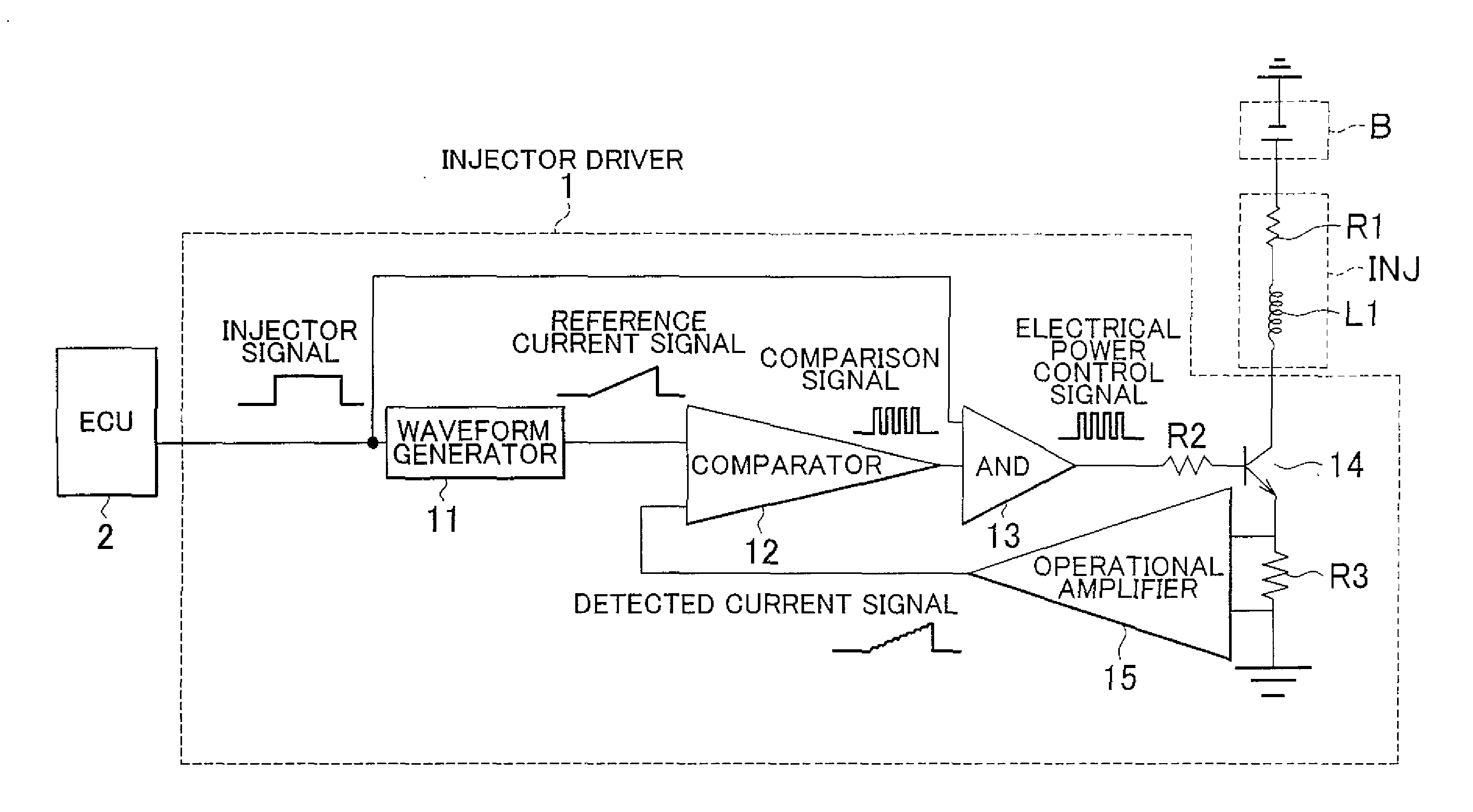
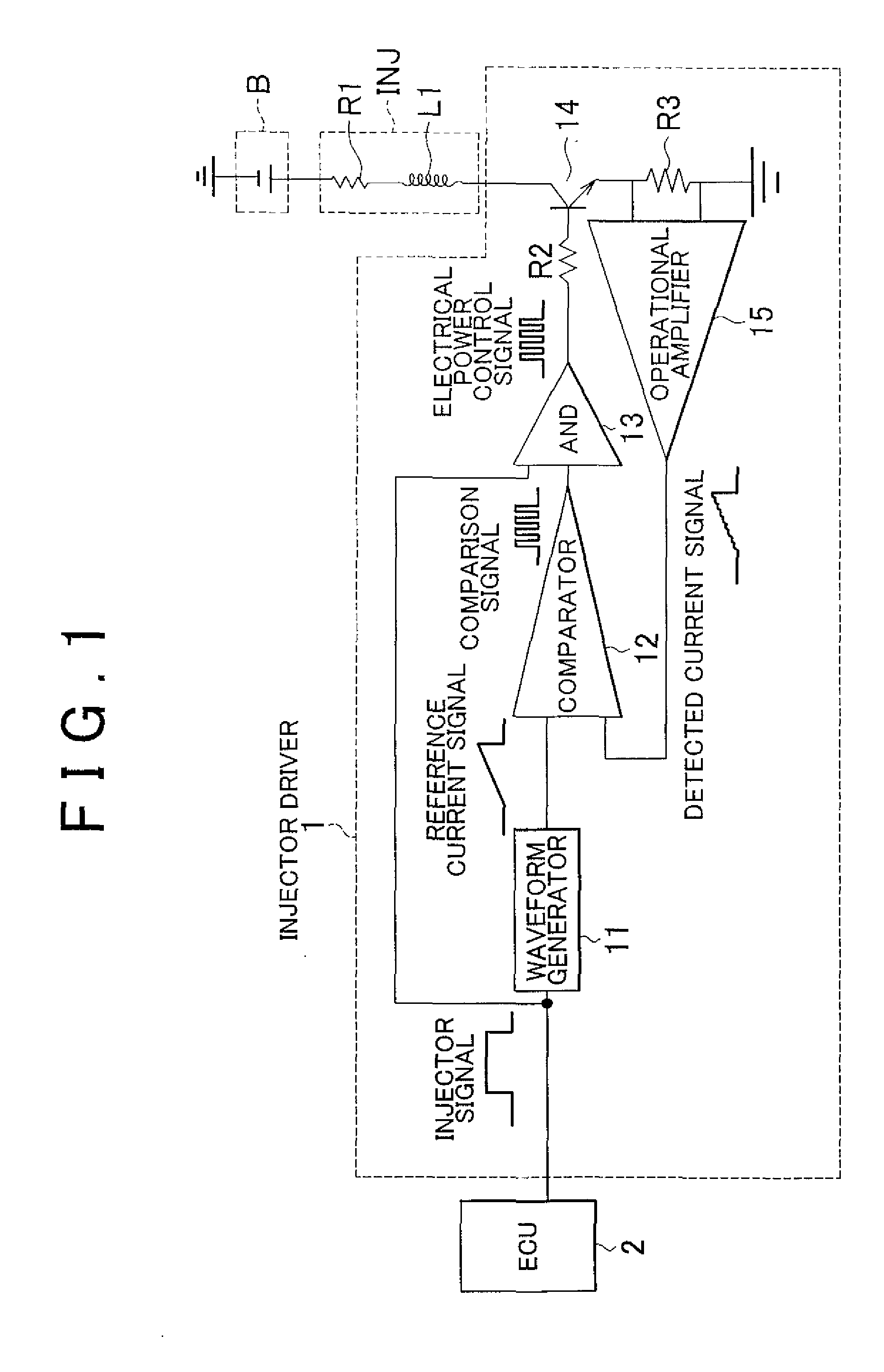
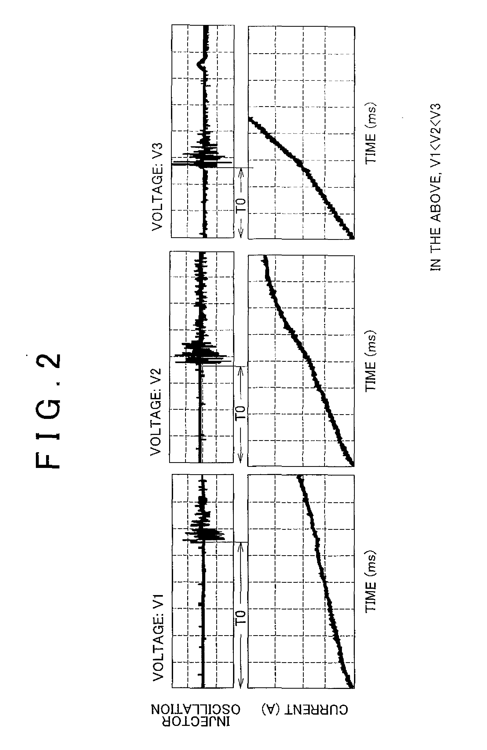
[0050]A configuration that approximates the reference current signal using a triangular wave may be adopted, and this will be described as the As shown in FIG. 2, because the injector current waveforms when the injector INJ is electrically powered are substantially triangular waves (straight lines), it is possible to use a signal that approximates the injector current waveform by a triangular wave as the reference current signal. Because a triangular wave can be generated by a simple configuration of RC elements or the like, this enables a simple and low-cost configuration for the waveform generator 11, enabling a low-cost configuration for the injector driver 1. Furthermore, the waveform approximated is not restricted to being a triangular wave, and can be, for example, a trapezoidal waveform or a curved waveform, and any waveform signal can be used as long as it is possible to evaluate the waveform as being substantially equivalent to the injector current waveform for the case in...

second embodiment

[0051]FIG. 6 describes the reference current signal in the present invention. In this drawing, (a) shows the INJ signal, (b) shows the operation of the injector INJ when the applied voltage is a high voltage, (c) shows the reference current signal when the applied voltage is a high voltage, (d) shows the injector current waveform when the applied voltage is a high voltage, (e) shows the operation of the injector INJ when the applied voltage is a low voltage, (f) shows the reference current signal when the applied voltage is a low voltage, and (g) shows the injector current waveform when the applied voltage is a low voltage, and Tc shows the valve-closing response time.

[0052]In this drawing, in the case in which the current value that increasing continuously exceeds a certain value (first current value) required for injector INJ operation, the reference current signal may be step-changed to a holding current value (second current value) that is set lower than the certain value (first...

third embodiment

[0054]The reference current signal may have a waveform having an increasing tendency that is substantially equivalent to that of the injector current waveform for the case in which the injector INJ is electrically powered under a specific condition (at a low battery voltage (+B) and prescribed operating condition), and this will be described as the present invention. In this manner, by making the waveform of the reference current signal equivalent to an actual waveform, it is possible to achieve coincidence in the operating state. In this case, the specific condition can be made a condition under which, in the injector INJ and engine, the injector current at an operating condition (at a normal engine rpm) at which the valve-opening response time T0 of the injector INJ is not a problem and the injector current has the slowest rate of rise.

[0055]The battery voltage (+B) varies depending upon the engine rpm and the size of the electrical load, and the coil resistance of the injector an...


PUM


Abstract

An injector driver and a drive method therefor wherein a reference current signal is generated that is synchronized to an injector valve signal for causing the injector to inject and that has a current increasing tendency substantially equivalent to an injector current waveform for the case in which a low voltage is applied to the injector, a current that flows in the injector is detected as a detected current signal, and the electrical powering of the injector is controlled by comparing the reference current signal with the detected current signal.

Description

INCORPORATION BY REFERENCE[0001]The disclosure of Japanese Patent Application No. 2006-198715 filed on Jul. 20, 2006 including the specification, drawings, and abstract, is incorporated herein by reference in its entirety.BACKGROUND OF THE INVENTION[0002]1. Field of the Invention[0003]The present invention relates to an injector driver, and specifically to an injector driver and a drive method therefor, which drive an injector of an internal combustion engine to which a battery directly supplies power.[0004]2. Description of the Related Art[0005]An electromagnetic fuel injector (hereinafter “injector”) is known as a conventional fuel injector in an internal combustion engine mounted aboard a vehicle such as an automobile. The injector includes a nozzle having a fuel injection port, a plunger, on the end of which is formed a valve (valve body), that is inserted into the nozzle and reciprocally moves freely therewithin, a return spring that imparts resilient force in the valve-closing...

Claims


Application Information

Patent Timeline
IPC IPC(8): F02D41/30
CPCF02D41/008F02D2041/2058F02D41/20
Inventor KOJIMA, SUSUMU
Owner TOYOTA JIDOSHA KK
Why Eureka
Try Eureka