Apparatus for cleaning a substrate having metal interconnects

Inactive Publication Date: 2008-01-24
KODERA MASAKO +4
View PDF8 Cites 5 Cited by
  • Summary
  • Abstract
  • Description
  • Claims
  • Application Information

AI Technical Summary

Benefits of technology

[0011] Therefore, there has been demand for a cleaning apparatus which can prevent interconnects made of aluminum or aluminum alloy on a substrate from being corroded, and it is an object of the present invention to provide such a cleaning apparatus.
[0012] Inventors of the present invention have made diligent studies in order to solve a problem of corrosion which occurs during a cleaning process of a substrate due to a potential difference between an interconnect metal such as aluminum or the like and a barrier layer metal on the substrate. As a result, the inventors have found that the potential difference between the interconnect metal and the barrier layer metal can be reduced by using various types of functional water as cleaning water for cleaning the substrate instead of using pure water, and have completed the present invention based on the findings in that the functional water is effective to prevent the corrosion from proceeding.
[0027] From the viewpoint of the potential difference between aluminum and another metal, the potential differences between aluminum and titanium and between aluminum and titanium alloy are minimized when using the oxygen-gas-dissolved water or a mixture of the oxygen-gas-dissolved water and the hydrogen-gas-dissolved water. Similarly, the oxygen-gas-dissolved water or a mixture of the oxygen-gas-dissolved water and the hydrogen-gas-dissolved water is effective for aluminum.

Problems solved by technology

Accordingly, when aluminum or aluminum alloy is used in combination with copper (Cu), tungsten (W), titanium (Ti), or their alloys, such aluminum or aluminum alloy is highly liable to suffer corrosion due to potential difference.
Therefore, if aluminum or aluminum alloy which basically comprises Al—Cu, and the above metal such as tungsten, titanium, or copper, or their alloys are simultaneously exposed on a surface of a semiconductor device and such a semiconductor device is processed, aluminum or aluminum alloy which basically comprises Al—Cu is highly likely to suffer corrosion.
However, there arises a problem that the aluminum interconnects are corroded in the cleaning process.
When the pure water is supplied to the aluminum interconnects and the barrier metal during the cleaning process, the aluminum interconnects suffer a serious problem in that the aluminum interconnects are corroded and dissolved due to the potential difference between the aluminum interconnects and the barrier metal which have been joined to each other.
However, if the substrate has fine circuit interconnects thereon, then the corrosion may cause defects such as disconnection, and hence the above problem becomes serious.

Method used


Image

  • Apparatus for cleaning a substrate having metal interconnects
  • Apparatus for cleaning a substrate having metal interconnects
  • Apparatus for cleaning a substrate having metal interconnects

Examples


first embodiment

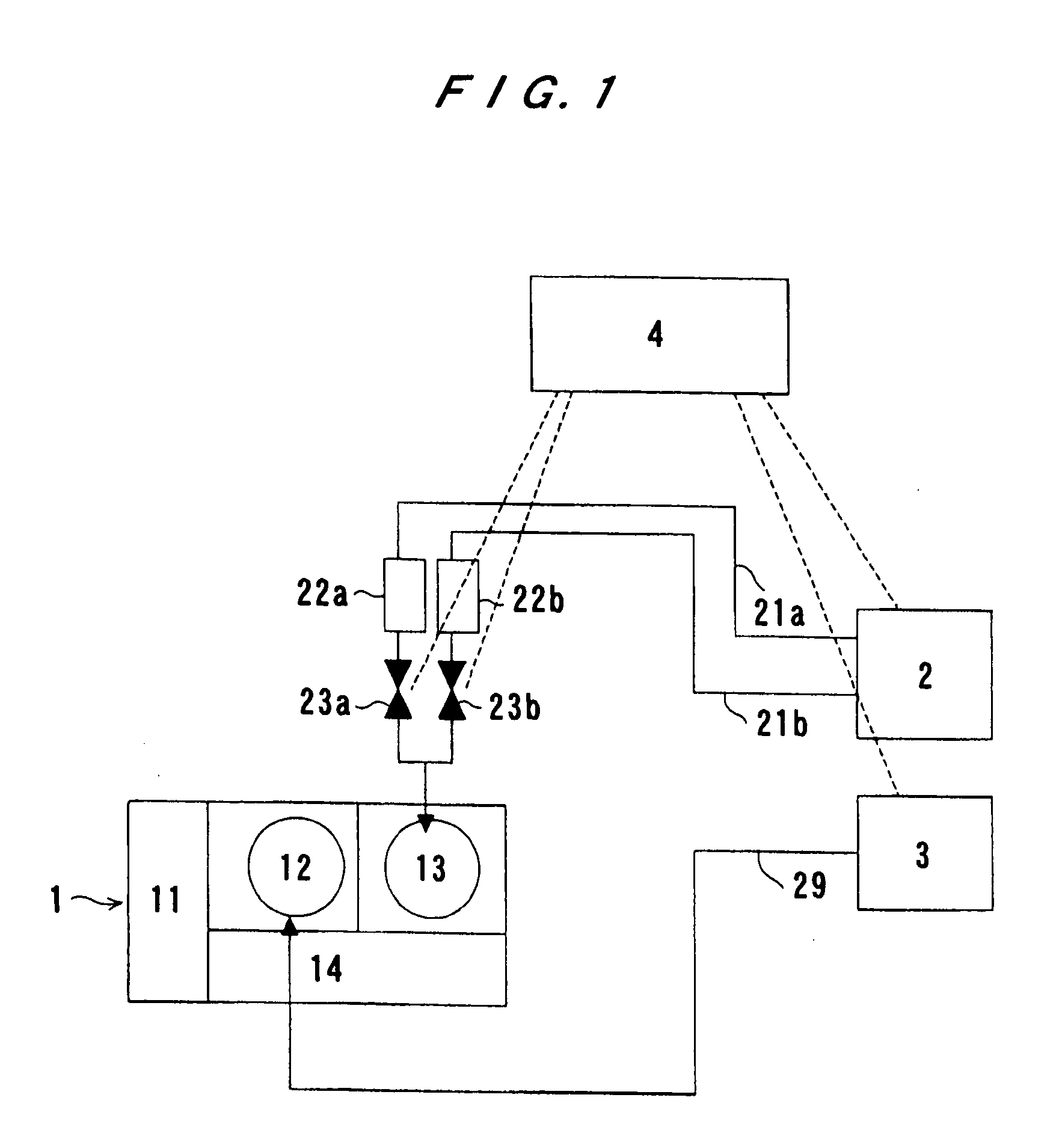
[0043]FIG. 1 is a schematic view showing a basic structure of a cleaning apparatus according to the present invention. As shown in FIG. 1, a cleaning apparatus comprises a cleaning unit 1 serving as a cleaning mechanism, a functional water producing unit 2 serving as a functional water supply mechanism, a chemical liquid supply unit 3, a controller 4, a pair of functional water supply pipes 21a, 21b, a pair of flow meters 22a, 22b, a pair of valves 23a, 23b, and a chemical liquid supply pipe 29. The cleaning unit 1 comprises a loading / unloading unit 11, a chemical processing module 12, a cleaning / drying module 13, and a transfer module 14.

[0044] A substrate to be cleaned is introduced into the cleaning unit 1 through the loading / unloading unit 11. The substrate is processed, e.g. etched, in the chemical processing module 12, and is then cleaned and dried in the cleaning / drying module 13. The substrate which has been cleaned and dried is transferred to a subsequent process by the tra...

second embodiment

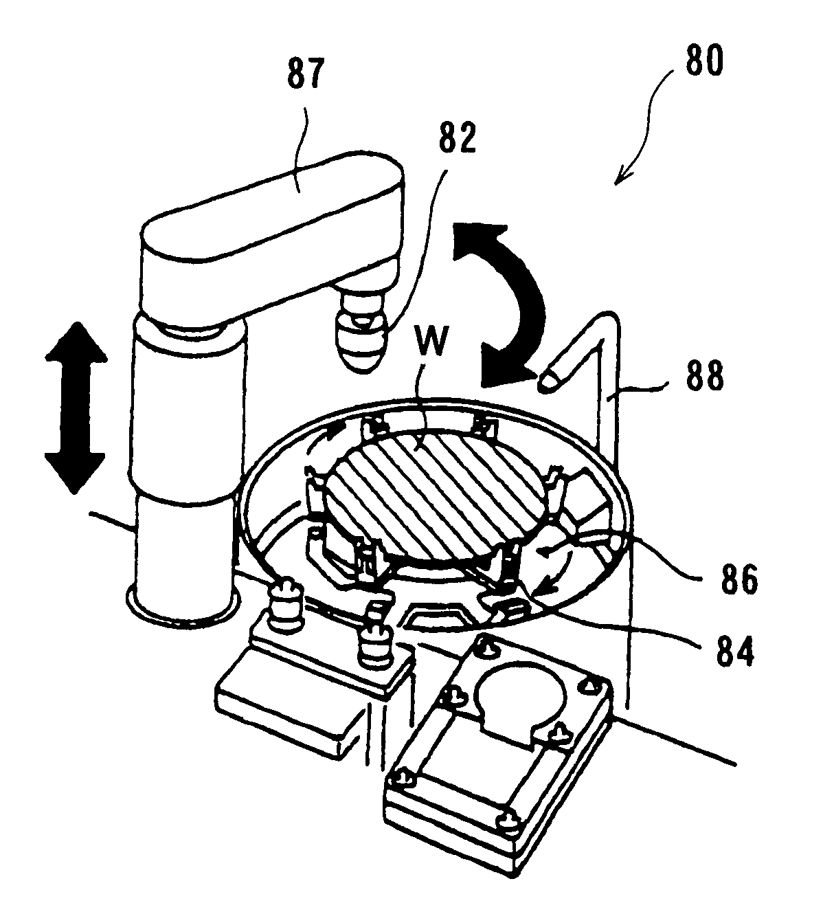
[0066]FIG. 7 is a schematic view showing an example of a cleaning / drying module incorporated in the cleaning apparatus according to the first or second embodiment of the present invention. A cleaning / drying module 70 shown in FIG. 7 performs a roll cleaning process while holding and rotating a substrate having interconnects. As shown in FIG. 7, the cleaning / drying module 70 comprises a plurality of rollers 73a, 73b for holding and rotating a substrate W, a plurality of roll-shaped cleaning members 74a, 74b for cleaning the substrate W, functional water supply nozzles 75a, 75b for supplying functional water to the substrate W, and chemical liquid supply nozzles 76a, 76b for supplying a chemical liquid such as an etching liquid or a chemical cleaning liquid to the substrate W. The rollers 73a, 73b hold a circumferential edge of the substrate W and rotate the substrate W about its own axis in a horizontal plan. The roll-shaped cleaning members 74a, 74b are brought into contact with an ...


PUM

PropertyMeasurementUnit
Electric potential / voltageaaaaaaaaaa

Abstract

The present invention relates to a cleaning apparatus which can reduce a potential difference between metals or alloys used to form interconnects on a substrate for thereby minimizing corrosion which may occur during and after a substrate cleaning process. The cleaning apparatus for cleaning a substrate having metal interconnects comprises a cleaning mechanism for cleaning the substrate, and a functional water supply mechanism for supplying functional water to the cleaning mechanism. The cleaning mechanism cleans a surface of the substrate with use of the functional water.

Description

BACKGROUND OF THE INVENTION [0001] 1. Field of the Invention [0002] The present invention relates to a cleaning apparatus for cleaning a substrate having metal interconnects for use in a precision electronic component such as a semiconductor device, and more particularly to a cleaning apparatus which can reduce a potential difference between metals or alloys used to form interconnects on a substrate for thereby minimizing corrosion which may occur during and after a substrate cleaning process. [0003] 2. Description of the Related Art [0004] Aluminum (Al) has been widely used as an interconnect material in a semiconductor device. Aluminum or aluminum alloy is a base metal having an extremely low potential compared with other metals (see “Metal Guidebook”, p 877, edited by The Japan Institute of Metals). Accordingly, when aluminum or aluminum alloy is used in combination with copper (Cu), tungsten (W), titanium (Ti), or their alloys, such aluminum or aluminum alloy is highly liable to...

Claims


Application Information

Patent Timeline
IPC IPC(8): C23G1/00B08B1/04B08B3/02H01L23/52B08B3/04B08B3/08B08B3/12C23G3/00H01L21/00H01L21/302H01L21/304H01L21/3205
CPCB08B1/04B08B3/02B08B3/04B08B3/08B08B3/12H01L21/67219H01L21/67046H01L21/67051H01L21/67057H01L21/67173C23G3/00B08B1/32C05F3/06
Inventor KODERA, MASAKOITO, KENYAKAMEZAWA, MASAYUKIHAMADA, SATOMIKATAKABE, ICHIRO
Owner KODERA MASAKO
Why Eureka
Try Eureka