
Embossed high modulus encapsulant sheets for solar cells

a solar cell and encapsulant technology, applied in the field of thermoplastic film or sheet, can solve the problems of difficult to choose an encapsulant layer, inconvenient to obtain edge seals, air can become trapped within the module, etc., and achieves less dirt accumulation, high de-airing efficiency, and low haze

Inactive Publication Date: 2008-01-24
DOW GLOBAL TECH LLC
View PDF49 Cites 82 Cited by
  • Summary
  • Abstract
  • Description
  • Claims
  • Application Information

AI Technical Summary

Benefits of technology

[0026]In one preferred embodiment, the encapsulant layer film and sheet of the present invention has an embossed pattern on each side (wherein the depth of the pattern on each side is in the range of from about 12 to about 20 micrometers). In a particularly preferred embodiment, there is an embossed pattern on one side of the encapsulant layer film and sheet that is orthogonal to the edges of the film and sheet, while the identical embossed pattern is slanted at some angle that is greater than or less than 90° to the edges: Offsetting the patterns in this manner can eliminate an undesirable optical effect in the film and sheeting.
[0032]Use of the present invention results in many advantages, such as less dirt accumulation, lower haze, and use of higher-efficiency de-airing and with less energy needed to compress the prelaminate when laminating (or at a controlled and desired level tailored for the pre-press / deairing process).
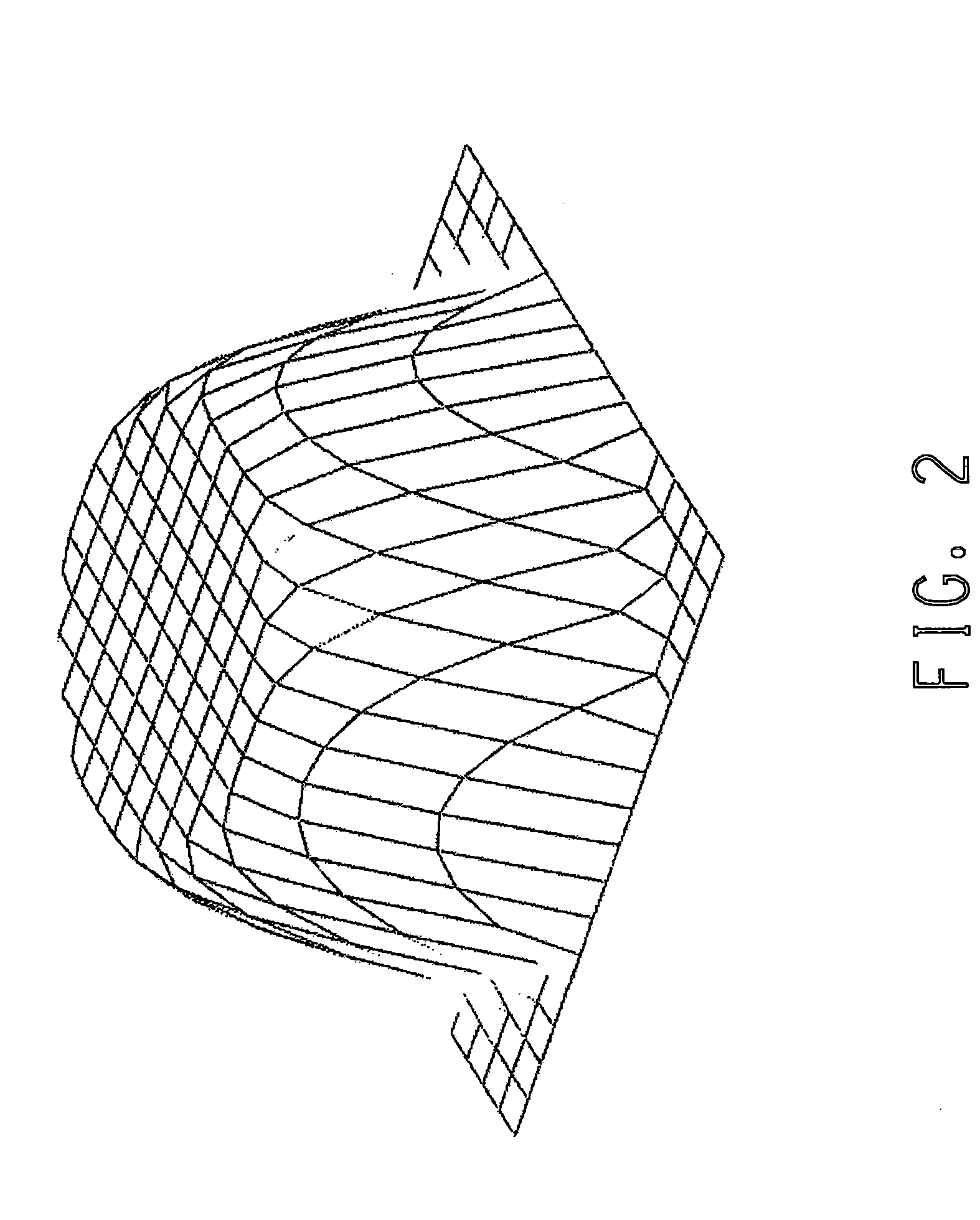
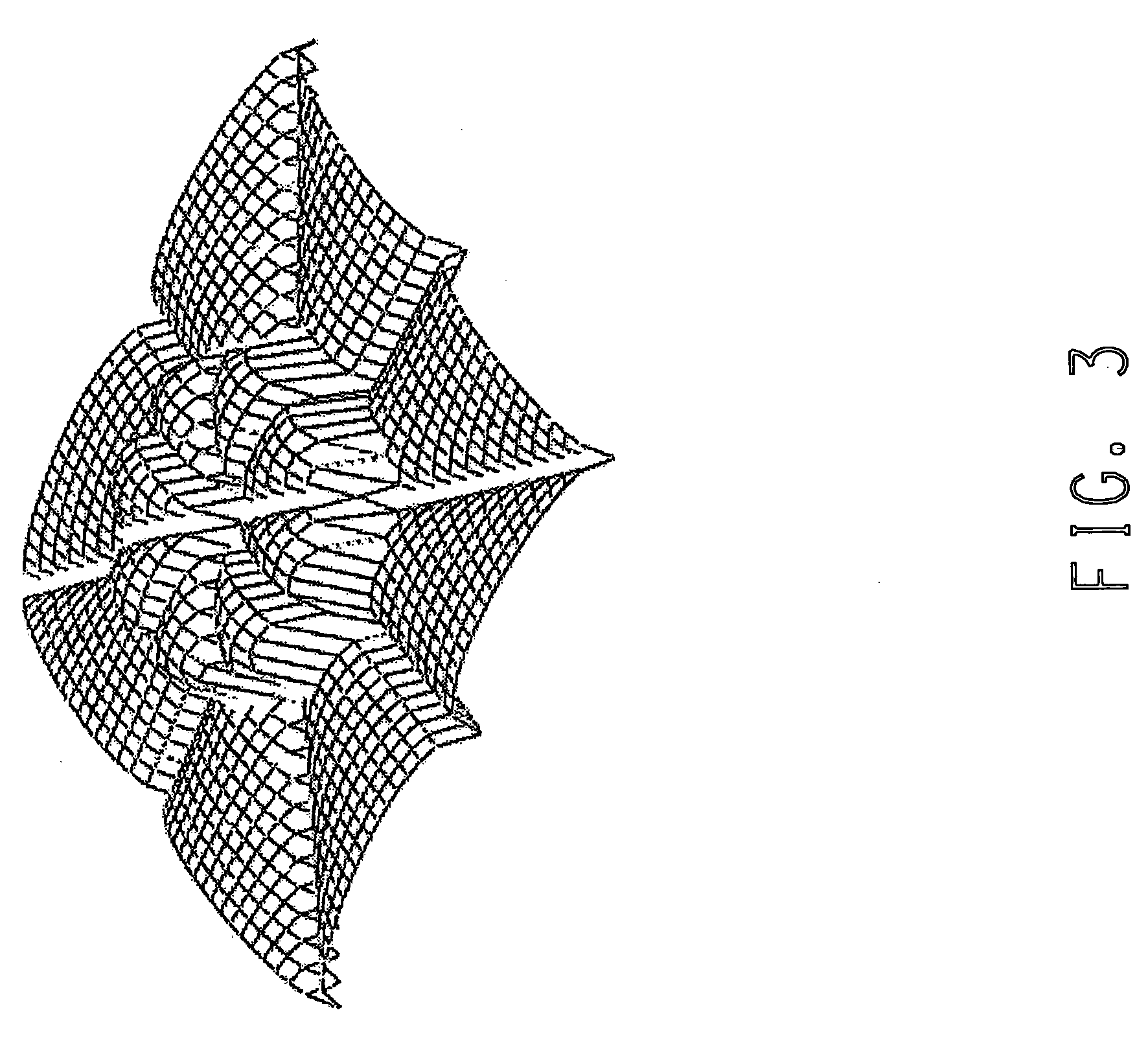
[0033]One example of a surface pattern of the present invention comprises projections upward from the base surface as well as voids, or depressions, in the encapsulant layer surface. Such projections and depressions would be of similar or the same volume, and located in close proximity to other such projections and voids on the encapsulant layer surface. The projections and depressions are preferentially located such that heating and compressing the encapsulant layer surface results in more localized flow of the thermoplastic material from an area of higher thermoplastic mass (that is, a projection) to a void area (that is, depression), wherein such voids would be filled with the mass from a local projection, resulting in the encapsulant layer surface being flattened. Localized flow of the thermoplastic resin material to obtain a flattened surface would require less of an energy investment than a more conventional pattern, which require flattening of a surface by effecting mass flow of thermoplastic material across the entire surface of the encapsulant layer. An important feature is the ability for the pattern to be flattened with relative ease as compared with the conventional art.

Problems solved by technology

Air can become trapped within the module during lamination.
These are generally objectionable for front sheet solar cell applications where the laminate functions as a transparent article, that is, being essentially free of optical defects (e.g. relatively low-haze thus providing a transparent front sheet to provide the maximum light transmission and, in turn, maximum solar cell efficiency).
It is sometimes difficult to choose an encapsulant layer with optimal features for pre-pressing, namely, rapid air removal and proper edge seal.
However, such encapsulant layers can make it inconvenient to obtain edge seal as more energy is generally required to compact the rough encapsulant layer.
If the edges of the pre-press are not completely sealed, air can penetrate the edge in the autoclaving step where the pre-press is heated under high pressure, and can cause visual defects in the laminate which is commercially unacceptable.
Laminators who use vacuum for de-airing in hot environments can have added difficulty.
On the other hand, relatively smooth encapsulant layers can lead to the edges sealing before sufficient air is removed, and can leave air trapped inside the pre-press.
Defects which occur after lamination are often more costly to rectify.
Due to these physical differences, surface patterns useful for EVA and plasticized PVB encapsulant layer sheeting may not be ideal for the ethylene copolymers which incorporate acid functionality and ionomers derived therefrom encapsulant layer sheeting, and vice versa.
However, the use of deep patterns with the higher modulus ethylene copolymers which incorporate acid functionality and ionomers derived therefrom interlayers can be problematic.
Also, the sharper melting range of an unplasticized, non-cured (non-crosslinked) encapsulant layer can lead to trapped air in the laminate.

Method used


Image

  • Embossed high modulus encapsulant sheets for solar cells
  • Embossed high modulus encapsulant sheets for solar cells
  • Embossed high modulus encapsulant sheets for solar cells

Examples


example 1

[0117]The embossed sheet structures noted below in Table 1 were prepared on a 24 inch width Sano multilayer coextrusion line equipped with embossing rolls utilizing common art sheet formation processes. This essentially entailed the use of an extrusion line consisting of a twin-screw extruder with a sheet die feeding melt into a roll stack. The rolls have an embossed surface pattern engraved into the metal surface which imparts to varying degrees a reverse image of the surface texture onto the polymer melt as it passes between and around the textured rolls. Both surfaces of the sheet were embossed with a pattern with the following characteristics; Mound average depth 21+ / −4 micron; Mound peak depth 25+ / −5 micron; Pattern frequency / mm 2; Mound width mm 0.350+ / −0.02 mm; and Valley width 0.140+ / −0.02 mm.

[0118]Surface roughness, Rz, can be expressed in microns by a 10-point average roughness in accordance with ISO-R468 of the International Organization for Standardization. Roughness mea...

example 2

[0121]The embossed sheet structures noted below in Table 2 were prepared as described above for Example 1.

TABLE 2Trilayer Sheet Structures.Outer LayersInner Layer Example(1 mil (0.026 mm) thick)(18 mils (0.4 mm) thick)AAIonomer 3Ionomer 1ABIonomer 4Ionomer 1ACIonomer 5Ionomer 1ADIonomer 3EBA 1AEIonomer 4EBA 1AFIonomer 5EBA 1AGIonomer 1Ionomer 6AHIonomer 1Blend 5AIIonomer 1EBA 1AJIonomer 1EMA 1EBA 1 was a poly(ethylene-co-n-butyl acrylate) with 27 weight percent n-butyl acrylate and a MI of 4 g / 10 minutes, (190 C., ISO 1133, ASTM D1238).Ionomer 6 was a poly(ethylene-co-iso-butyl acrylate-co-methacrylic acid) with 10 weight percent iso-butyl acrylate and 10 weight percent methacrylic acid and neutralized with 16 percent zinc ion with a MI of 10 g / 10 minutes, (190 C., ISO 1133, ASTM D1238).Blend 5 contains 50 weight percent of Ionomer 1 and 50 weight percent of Ionomer 6.EMA 1 was a poly(ethylene-co-methyl acrylate with 30 weight percent methyl acrylate.

[0122]A variety of laminate stru...

example 3

[0123]The embossed sheet structures noted below in Table 3 were prepared as described above for Example 1.

TABLE 3Trilayer Sheet Structures.Outer LayersInner LayerExample(5 mil (0.13 mm) thick)(10 mils (0.25 mm) thick)BAIonomer 3Ionomer 1BBIonomer 4Ionomer 1BCIonomer 5Ionomer 1

[0124]A variety of laminate structures (4 inch by 4 inch) were produced from each embossed sheet described above to demonstrate various solar cell structures as described above for Example 1. The laminate structures included glass / Example / glass, fluoropolymer film / Example / glass, aluminum sheet / Example / glass, aluminum sheet / Example and glass / Example.


PUM

PropertyMeasurementUnit
Lengthaaaaaaaaaa
Lengthaaaaaaaaaa
Lengthaaaaaaaaaa

Abstract

A thermoplastic film or sheet having a thickness of about 1 mil (0.026 mm) to about 20 mils (0.51 mm) containing a surface embossed layer comprising a copolymer of alpha olefin(s) with alpha, beta ethylenically unsaturated carboxylic acid comonomer(s), ionomers derived therefrom and combinations thereof useful for making solar cell laminates, wherein the surface is embossed with a pattern which provides channels for de-airing, the channels having depth of about 20 microns or less, a width of about 30 microns to about 300 microns and spaced about 0.1 mm to about 1 mm apart, and use thereof in photovoltaic cells and the manufacture thereof.

Description

FIELD OF THE INVENTION[0001]The present invention relates to thermoplastic film or sheets containing a layer comprising copolymers of alpha olefin(s) with alpha, beta ethylenically unsaturated carboxylic acid comonomer(s), or ionomers derived therefrom (as well as combinations thereof) and their use in solar cells.BACKGROUND OF THE INVENTION[0002]Photovoltaic (solar) cell modules are units that convert light energy into electrical energy. Typical or conventional construction of a solar cell module consists of at least five structural layers. The layers of a conventional solar cell module are constructed in the following order starting from the top, or incident layer (that is, the layer first contacted by light) and continuing to the backing (the layer furthest removed from the incident layer): (1) incident layer / (2) frontsheet encapsulant layer / (3) voltage-generating layer / (4) backsheet (second) encapsulant layer / (5) backing layer. The function of the incident layer is to provide a ...

Claims


Application Information

Patent Timeline
IPC IPC(8): H02N6/00
CPCB32B17/10587B32B17/10743B32B17/10853Y02E10/50B32B27/32H01L31/048B32B17/10862H01L31/0481
Inventor ANDERSON, JERREL C.HAYES, RICHARD ALLENLENGES, GERALDINE M.SMITH, CHARLES ANTHONY
Owner DOW GLOBAL TECH LLC
Learn More