Non Uniform Water Distribution System for an Evaporative Cooler

a water distribution system and cooler technology, applied in the direction of machines/engines, combustion air/fuel air treatment, combustion gas purification/modification, etc., can solve the problems of lowering the temperature of the air, wear and tear of inexpensive pumps, and relatively rapid changes of pump delivery heads, etc., to achieve high cooling efficiency and high cycles of concentration

Inactive Publication Date: 2008-01-24
AZ EVAP
View PDF50 Cites 36 Cited by
  • Summary
  • Abstract
  • Description
  • Claims
  • Application Information

AI Technical Summary

Benefits of technology

[0025] The evaporative cooler is a unique arrangement of a combination of specially selected fluid components that includes flow control valves, spray bars, spray bar orifices, spray bar distribution channels, media front and rear distribution plates, and distribution caps yielding a configuration that produces a water application profile that is adjusted to match the heat load introduced to the media by the air to be evaporatively cooled. The water evaporation rate is a direct function of this heat load profile. Applying water in this profile is achieved by a water distri...

Problems solved by technology

The movement of the heat from the air to the water vapor happens without a change in air volume or air pressure and results in a lowering of the temperature of the air.
The conventional evaporative cooler does not attempt to account for or control any of these process variables to optimize efficiency and account for such variation in environmental conditions.
These inexpensive pumps are not precision pieces of equipment and wear quickly as the debris is recirculated.
This deterioration of the pump leads to fairly rapid changes in the delivery head for the pump.
This change in the output of the pump renders it difficult to regulate the water flow across the media.
The end result is an uneven water distribution and occasionally dry strips on the media.
This excess amount of water occupies space in the air flutes of the media which reduces airflow and increases the velocity in the air passage increasing the potential for water entrainment and carryover.
Once formed on the media it forms an insulating layer reducing the saturation efficiency and clogs the air and water distribution channels.
Second, the flow volume of water must be sufficient to wet the media completely and yet the flow must be limited so as to avoid wasting large amounts of water.
These systems have the significant disadvantage of using too much water or from using an insufficient amount of water resulting in drying out and scaling of the media.
These limitations have limited their commercial acceptability.
Furthermore...

Method used


Image

  • Non Uniform Water Distribution System for an Evaporative Cooler
  • Non Uniform Water Distribution System for an Evaporative Cooler
  • Non Uniform Water Distribution System for an Evaporative Cooler

Examples


Embodiment Construction

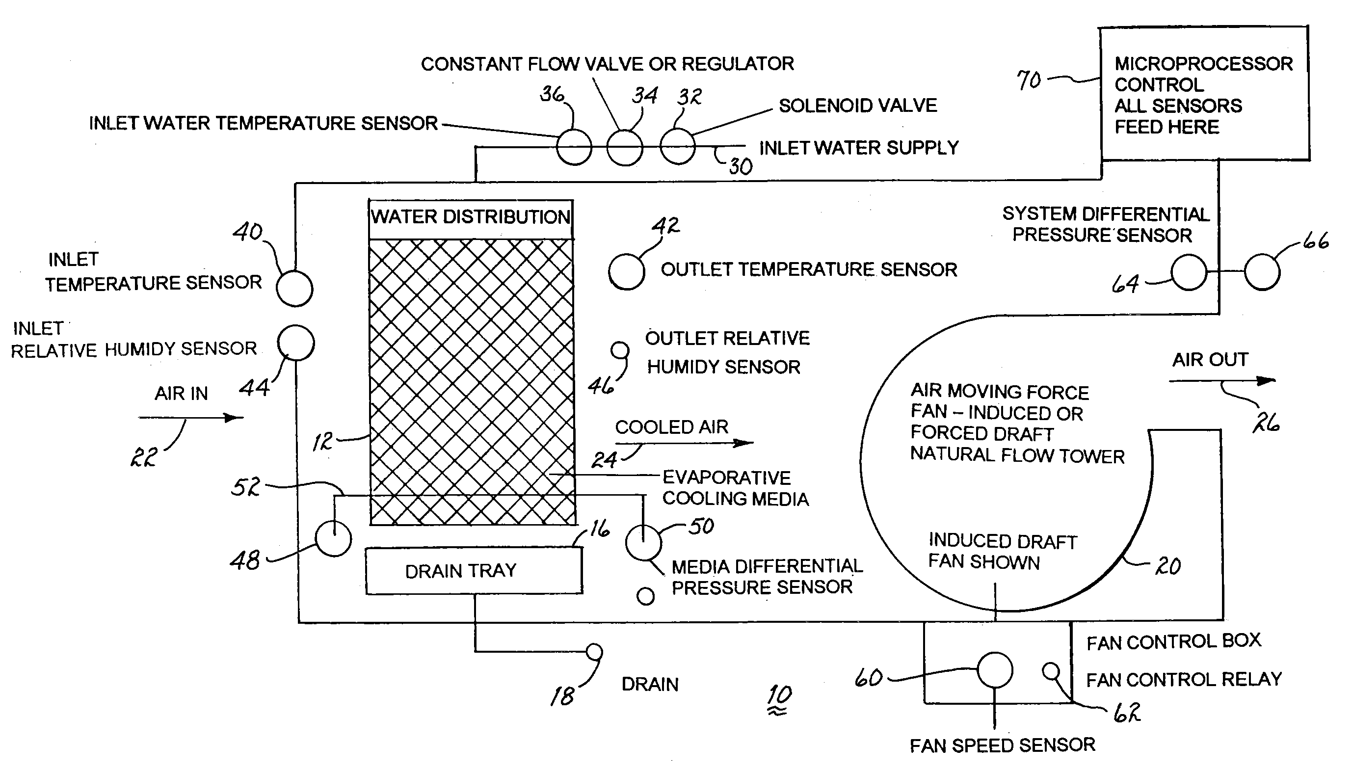
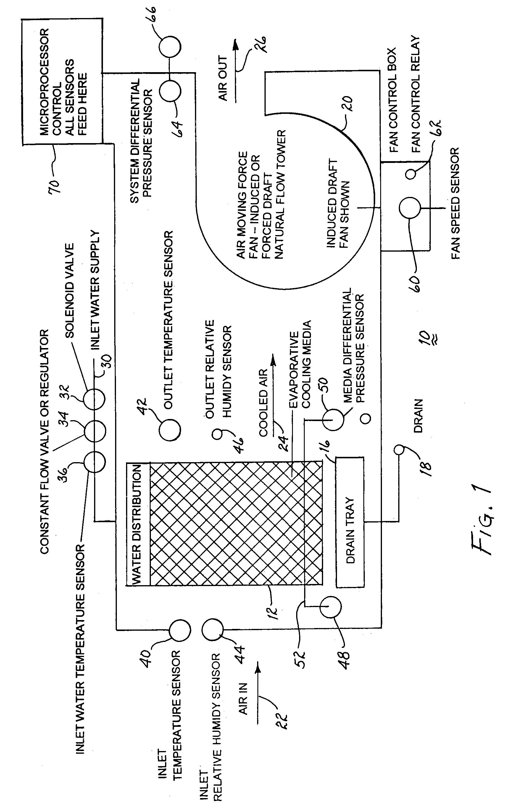
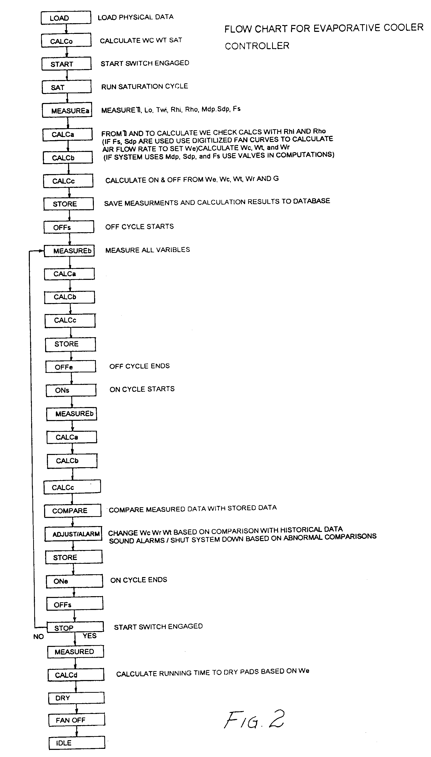
[0049] The psychrometric chart provides information such that knowing the inlet dry bulb temperature, the inlet wet bulb temperature, altitude, and volumetric flow rate of the air one can determine the amount of moisture that can be added to this air and the resulting leaving air dry bulb and wet bulb temperatures. The chart in effect uses thermal and mass balance equations and algorithms to yield this information. For an evaporative cooler, the mass balance and associated psychrometric equations are solved using the inlet conditions and the capabilities of the equipment. The evaporation rate is dependent on the difference between the local conditions which vary along the depth of the media and the wet bulb temperature. Existing once through evaporative coolers attempt to measure and control water application using the inlet temperature, the pad or media temperature, the outlet temperature and relative humidity or pad / media relative humidity, but fail to do so with algorithms correl...


PUM

PropertyMeasurementUnit
Diameteraaaaaaaaaa
Diameteraaaaaaaaaa
Diameteraaaaaaaaaa

Abstract

An evaporative cooler, including one or more media, distributes water from a source of water to each media through a constant flow valve. A distribution unit at each media includes a pair of spray bars for spraying water through two rows of uniformly spaced apertures disposed in each spray bar. A spray bar channel associated with each spray bar distributes the streams of water impinging thereupon from one row of apertures to the underlying media in specific locations. A distribution cap associated with each spray bar distributes streams of water impinging thereupon to the front and back edges of the underlying media. The water dripping from the media is drained. A fan or other air moving device draws air through the media to obtain cooled air resulting from evaporation of water flowing downwardly along the media. A microprocessor controller, responsive to any of one or more sensors for sensing the temperature of the air flowing into and out of the media, the relative humidity of the air flowing into and out of the media, the pressure differential between the upstream and downstream sides of the media, the temperature of the water flowing to the spray bars, the fan speed, and the pressure differential between the downstream side of the media and the downstream side of the fan, controls the flow of water and the fan speed.

Description

CROSS REFERENCE TO RELATED APPLICATIONS [0001] This application is a continuation-in-part of an application entitled “Water Distribution System For An Evaporative Cooler”, filed Dec. 1, 2006 and assigned Ser. No. 11 / 569,944, which is a national phase application based on a Patent Cooperation Treaty application entitled “Water Distribution System For An Evaporative Cooler,” Serial No. PCT / US04 / 43748, filed Dec. 23, 2004, which claims priority to an earlier filed application, entitled “Water Distribution System For An Evaporative Cooler,” Ser. No. 10 / 862,040, filed Jun. 4, 2004, now U.S. Pat. No. 7,131,639. [0002] Moreover, the present application includes subject matter disclosed in and claims priority to a provisional application entitled “Evaporative Cooler With Dual Water Inflow”, filed Jan. 18, 2007 and assigned Ser. No. 60 / 885,557 describing an invention made by the present inventors.BACKGROUND OF THE INVENTION [0003] 1. Field of the Invention [0004] The present invention relate...

Claims


Application Information

Patent Timeline
IPC IPC(8): F24F6/02B01F3/04
CPCF24F5/0035Y02B30/545F24F6/043Y02B30/54Y10S261/46
Inventor KAMMERZELL, LARRY L.KAMMERZELL, DONALD L.
Owner AZ EVAP
Why Eureka
Try Eureka