Running Gear And Production Method

a technology of running gear and production method, which is applied in the direction of gearing, hoisting equipment, instruments, etc., can solve the problems of thermo-treatment of materials which are not easy to process, and achieve the effects of increasing processing speed, increasing root rigidity, and increasing processing speed

Inactive Publication Date: 2008-01-31
DAIMLER AG
View PDF7 Cites 8 Cited by
  • Summary
  • Abstract
  • Description
  • Claims
  • Application Information

AI Technical Summary

Benefits of technology

[0007]It is particularly advantageous when the feedability and deformability in one direction are taken into account when the geometry of the workpiece is chosen. This makes it possible to mass-produce the workpiece and the running gear.
[0009]In particularly advantageous fashion, stiffening ribs or stiffening covers can be provided, extending between at least two teeth. This way, the teeth have a very high bending resistance, so the root stability is also very high. Geometric reinforcing measures are also possible, in which conventional milling, grinding, or lapping crosses or penetrates the tool paths. The increased bending resistance brings benefits with respect to the running smoothness and useful life of the running gear. Advantageously, larger gains in torque transmission capability can be achieved than with, for example, other methods for optimizing the tooth geometry or surface coatings.
[0011]In a particularly advantageous fashion, a reinforcing element, for instance a reinforcing cover, can be provided on the back of the bevel gears, which leads to an appreciable gain in root rigidity.
[0015]A particular advantage of the processing method of the invention is that it does not require separate tool entry and exit for milling, grinding, or lapping. Therefore, in the processing method of the invention, complex running gear geometries do not need to be designed with multi-part subassemblies that have to be joined after the teeth are finished, as is the case with a ring gear of a differential casing, for example. In the case of the one-piece ring gear differential casing unit, an annular electrode can be provided, which is pulled over the differential casing coaxially to same and which finishes it electrochemically in one process step while in a position in the region of the previously processed running gear. Subassembly interfaces still needed today can be eliminated not only in the case of the differential casing. All the measures made possible by the method of the invention add up to a large cost saving potential.
[0016]A particularly advantageous result of the invention is that it opens up the possibility of processing machines for producing partially complex toothing geometries which employ the method of the invention. Such processing machines of the invention having one or more electrodes and an electrolyte bath are less expensive than the gear machines which work by cutting, which are common today. As a result, the running gear manufacturers are less dependent on a few machine vendors.
[0017]The steering gear box is a particularly advantageous field of application of the invention. It is possible to preforge or precast the differential casing with the ring gear in a component with a size of a few tenths of a mm. This eliminates a complicated, highly stressed, and expensive interface.

Problems solved by technology

One such material which is not easy to process is thermo-treated austenitic ductile iron material.

Method used


Image

  • Running Gear And Production Method
  • Running Gear And Production Method
  • Running Gear And Production Method

Examples


Embodiment Construction

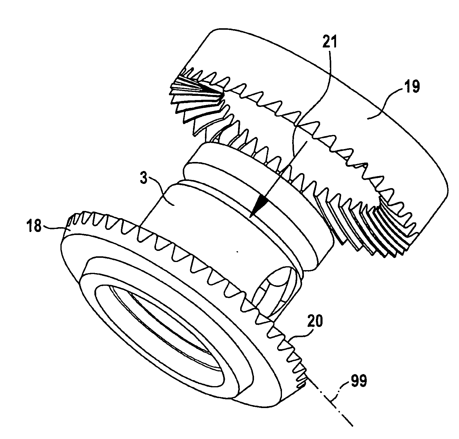
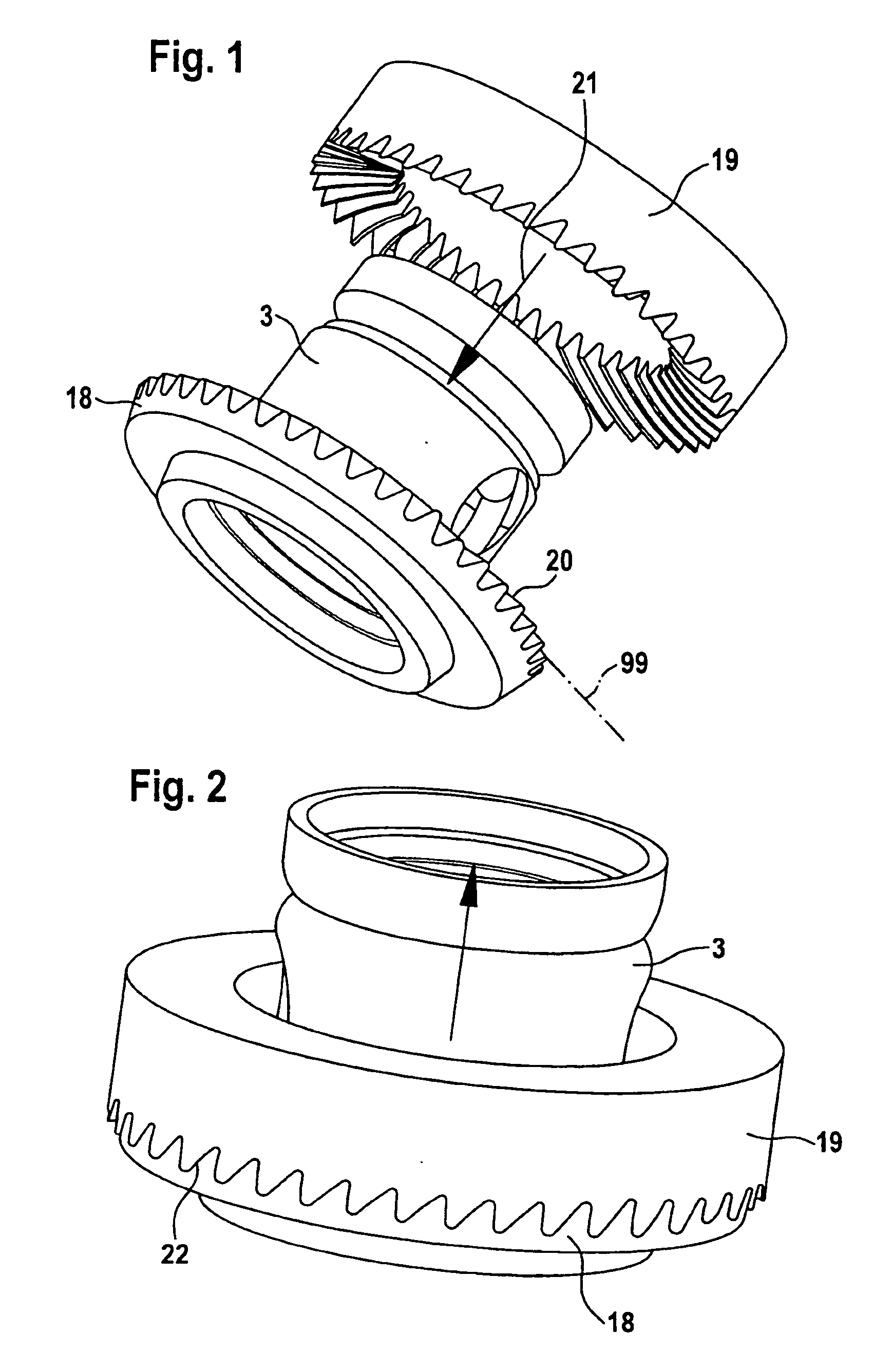
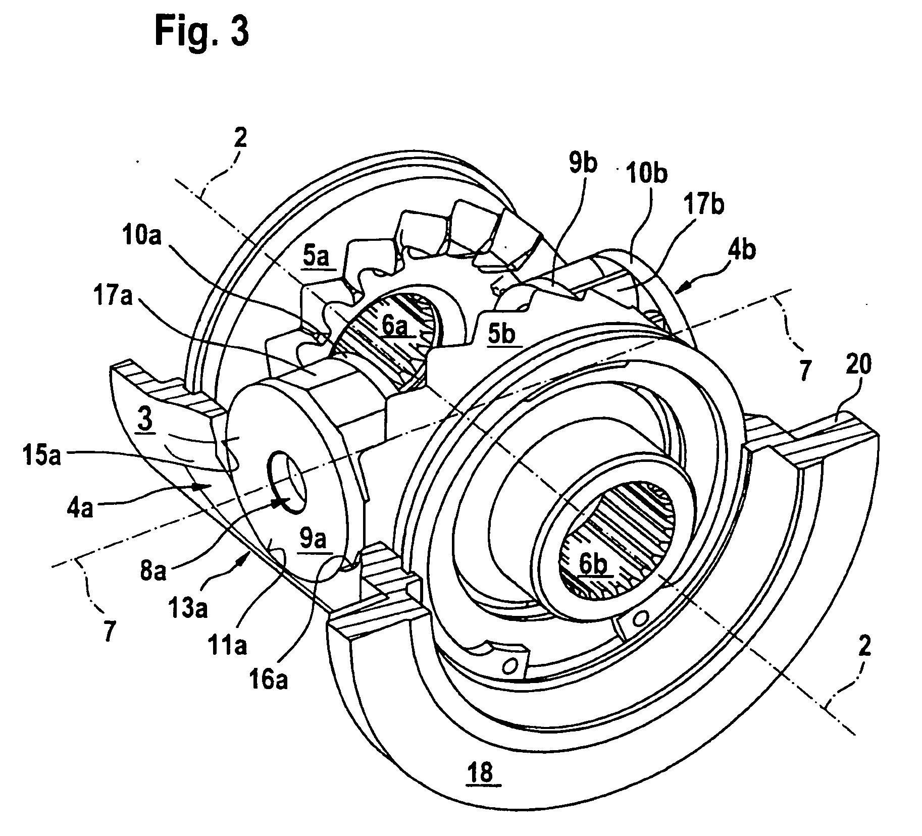
[0041]FIG. 1 shows a housing 3 of a crown gear differential. The crown gear differential is constructed in the assembled condition represented in FIG. 3 and FIG. 4. A ring gear 18 is formed on the housing 3. A running gear 20 of the ring gear 18 is an hypoid toothing. The housing 3 with the ring gear 18 can be produced from a signal part in particular by[0042]precision forging or[0043]precision casting.

The housing 3 is preforged or precast from a thermo-treated austenitic ductile iron material with a size of 3 / 10 mm to 5 / 10 mm.

[0044]In an electrochemical gear machine, which is not represented, an electrode 19 is aligned coaxial to a rotational axis of the housing 3. The electrode 19 consists of an annular base body having substantially a negative shape of the running gear 20 incorporated in the side that faces the running gear 20. The electrode 21 is moved to the running gear 20 of the ring gear 18 coaxially according to arrow 21, until only a flushing gap 22 of approx. 1 / 100 mm rem...


PUM

PropertyMeasurementUnit
shapeaaaaaaaaaa
voltageaaaaaaaaaa
negative shapeaaaaaaaaaa

Abstract

A running gear toothing for gearwheels and a process for producing such running gear is provided. In order to be able to work complex shapes (e.g. reinforcing ribs) into running gear, a preforged or precast gearwheels are produced oversized, and are then finished using an electrochemical erosion process. The invention eliminates complex machining operations and permits gear teeth finishing in highly spaced-constrained applications, thereby eliminating the need for production and assembly complex multi-component gears.

Description

[0001]This application is a national phase application of International application PCT / EP2004 / 013262 filed Nov. 23, 2004 and claims the priority of German application No. 103 58503.6, filed Dec. 13, 2003, the disclosures of which are expressly incorporated by reference herein.BACKGROUND AND SUMMARY OF THE INVENTION[0002]The invention relates to a running gear and to a method for producing a running gear.[0003]German patent document DE-OS 29 26 255 describes a toothed gearwheel which is constructed with a running gear and a shifting gear. The shifting gear is produced electrochemically or electroerosively or by precision forging. The shifting gear is deposited electrochemically or electroerosively.[0004]The object of the invention is to create a large geometric tolerance for running gears.[0005]It is possible to produce hypoid toothing or other complex running gear geometries by either precision forging or casting.[0006]Cost-effective running gears can be produced with a large geome...

Claims


Application Information

Patent Timeline
Patent Type & Authority Applications(United States)
IPC IPC(8): B21K1/30F16H1/20F16H55/02B23H3/00B23H9/00B23P15/14F16H48/08F16H55/06F16H55/17
CPCB23H3/00Y10T29/49476B23H9/003B23P15/14F16H48/08F16H48/40F16H55/06F16H55/17F16H2048/082F16H2048/087F16H2048/102F16H2048/385Y10T74/19698Y10T74/20756B23H9/00
Inventor ZEISE, DIRK
Owner DAIMLER AG
Why Eureka
Try Eureka