Cutter Wheel, Manufacturing Method for Same, Manual Scribing Tool and Scribing Device

a manufacturing method and tool technology, applied in the field of cutter wheels, can solve the problems of uneven gap between substrates, difficult to turn over glass substrates g, etc., and achieve the effects of excellent biting, excellent edge bite, and control of processing precision

Inactive Publication Date: 2008-01-31
MITSUBOSHI DIAMOND IND CO LTD
View PDF11 Cites 10 Cited by
  • Summary
  • Abstract
  • Description
  • Claims
  • Application Information

AI Technical Summary

Benefits of technology

[0026]In a cutter wheel for scribing a brittle material substrate according to the present invention, a V-shaped ridge line part is formed along the circumferential part of a disk-like wheel as an edge, at least one notch is engraved in the above described ridge line part and notches as that described above are created in the entirety of the periphery of the above described ridge line part with a pitch of more than 100 μm, preferably with a pitch of more than 200 μm. As a result, excellent biting can be gained on the surface of a brittle material substrate.
[0027]In the cutter wheel for scribing a brittle material substrate according to this invention, the above described V-shaped ridge line part is formed of two slanted surfaces which converge toward the outside in the direction of the radius, and the circumferential ridge line formed of the above described two converging slanted surfaces has microscopic unevenness where the average coarseness Ra along the center line of the above described unevenness exceeds 0.40 μm. Here, “average coarseness Ra along the center line” in this invention is one of the parameters for prescribing the coarseness on the surface of industrial products prescribed in JIS B 0601, and an arithmetic average value on the surface of objects sampled at random.
[0028]In the case where a number of notches are created in the entirety of the periphery of the above described ridge line part with a random pitch and / or depth, control of the processing precision at the time of engraving of notches becomes almost completely unnecessary, and excellent bite of the edge can be gained.
[0029]In accordance with a manufacturing method for a cutter wheel for scribing a brittle material substrate according to this invention, when at least one notch is engraved in the V-shaped ridge line part of a cutter wheel where the above described ridge line part is formed along the circumferential part of a disk-like wheel as an edge, a cutter wheel is rolled over a tool for engraving notches made of a material which is harder than the ridge line part of the above described cutter wheel where at least one protrusion is formed while making contact with protrusions as that described above while pressure is applied. As a result, the equipment required for engraving notches can be simplified, and the time for work can be significantly shortened in comparison with the prior art. In addition, this work of engraving is not affected by any difference in the experience and personal ability of the workers, and thus, the productivity becomes high.

Problems solved by technology

Accordingly, it has become difficult to turn over glass substrate G after scribing and convey glass substrate G to the breaking device as described above.
Therefore, when glass substrate G is turned over using, for example, a vacuum suction means, for breaking after liquid crystal has been injected through dripping, the space between the two substrates partially expands, causing a problem such that the gap between the substrates becomes uneven.

Method used


Image

  • Cutter Wheel, Manufacturing Method for Same, Manual Scribing Tool and Scribing Device
  • Cutter Wheel, Manufacturing Method for Same, Manual Scribing Tool and Scribing Device
  • Cutter Wheel, Manufacturing Method for Same, Manual Scribing Tool and Scribing Device

Examples


embodiment 1

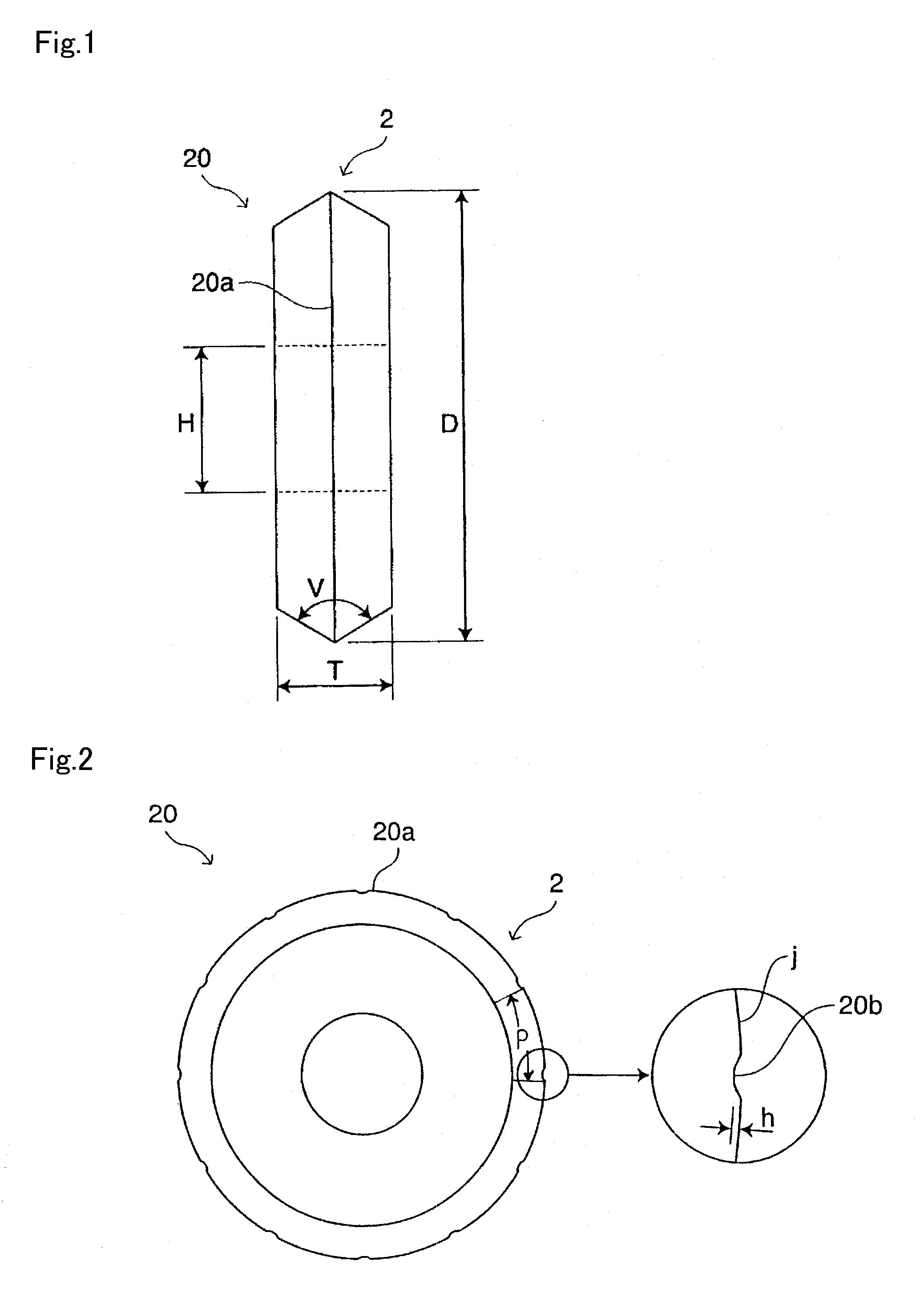
[0068]A cutter wheel 20 according to an embodiment of this invention is described in reference to FIGS. 1 and 2.

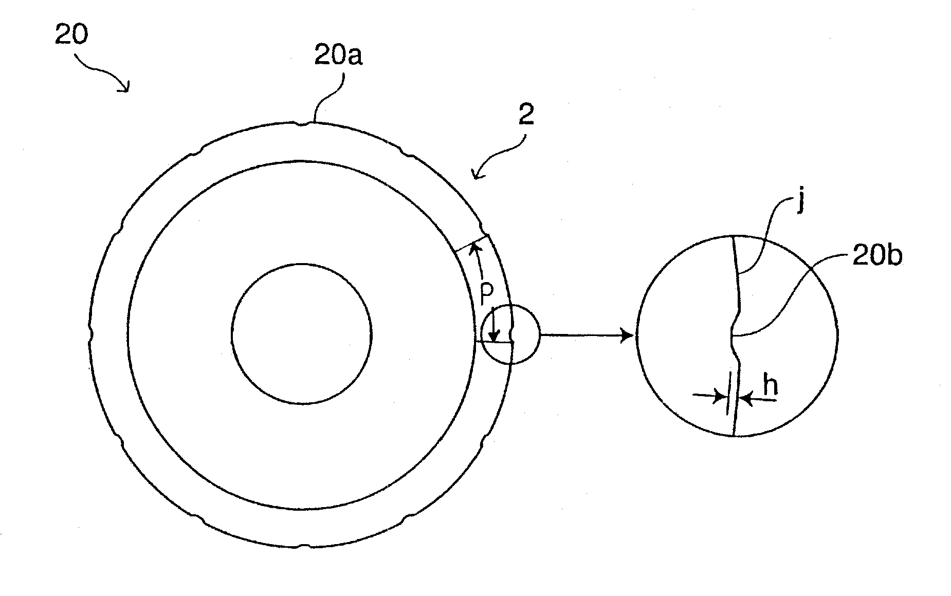
FIG. 1 is a front diagram showing cutter wheel 20 as viewed in the direction perpendicular to the rotational axis, and FIG. 2 is a side diagram showing the cutter wheel of FIG. 1.

Here, cutter wheel 20 is a cutter wheel which can be mounted on a chip holder 140 in the conventional scribing device 100 described in reference to FIG. 13.

As shown in FIG. 1, cutter wheel 20 is in disk form with an outer diameter D of the wheel and a thickness T of the wheel, and an edge 2 with an edge angle V is formed in the outer peripheral part of the wheel.

[0069]Furthermore, as shown in FIGS. 1 and 2, in cutter wheel 20, unevenness is created in a ridge line part 20a where edge 2 is formed. That is to say, U-shaped or V-shaped notches 20b are created in this example, as shown in the diagram showing an enlarged part of FIG. 2. Notches 20b are created by providing notches having a depth h in t...

experiment 1

[Experiment 1]

[0085]In Experiment 1, the pitch of notches 20b in cutter wheel 20 was changed by 100 μm, and the degree of biting of the edge (ease of sliding) when inside cutting was carried out on improved large scale glass, which is the object of cutting, as described above was examined.

[0086]The conditions for Experiment 1 are shown in the following.

glass substrate G1 which is object of cutting: non-alkaline glass (single plate of glass having a thickness of 0.7 mm)

glass substrate G2 which is object of cutting: improved large scale glass (single plate of glass having a thickness of 0.63 mm)

[Cutter Wheel]

[0087]material: hard metal; outer diameter D: 3.0 mm; thickness T: 0.65 mm; diameter of hole for axis: 0.8 mm

[0088]pitch P of notches: 100 μm to 400 μm (circumference equally divided into 94 to 23)

[0089]depth h of notches: 2 μm to 3 μm

[0090]angle V of edge: 120°

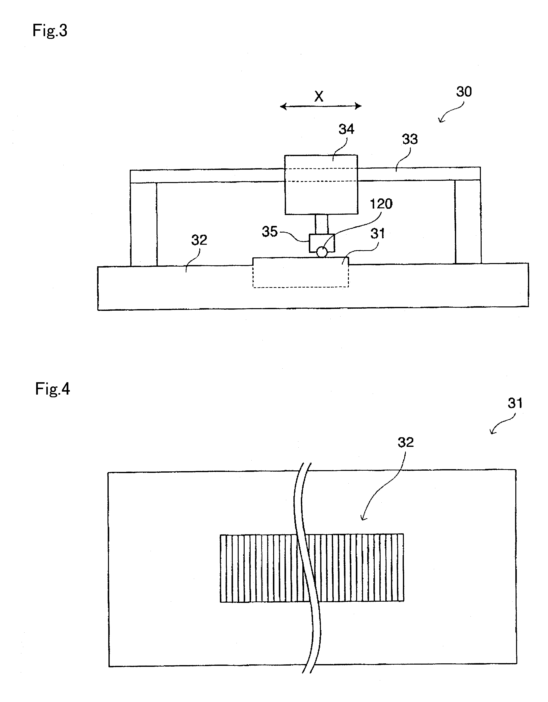
[0091]method for engraving notches: above described rolling method using tool for engraving notches 31

[Scribing Device]

[0...

experiment 2

[Experiment 2]

[0100]In Experiment 2, inside cutting was carried out on a predetermined cut region in improved large scale glass as that described above using cutter wheel 120 having an edge without notches and cutter wheel 20 having notches according to this invention, and the state of scribing at this time was examined.

[0101]Conditions in Experiment 2 are shown in the following.

[0102]glass substrate which object of cutting: improved large scale glass (single plate of glass having thickness of 0.63 mm)

[Cutter Wheel]

[0103]material: hard metal and sintered diamond; outer diameter D: 3.0 mm; thickness T: 0.65 mm; diameter of hole for axis H: 0.80 mm

[0104]pitch P of notches: 300 μm (circumference equally divided into 31)

[0105]depth h of notches: 2 μm to 3 μm

[0106]angle V of edge: 120°

[0107]method for engraving notches: above described rolling method using tool for engraving notches 31

[Scribing Apparatus]

[0108]MS type, made by Mitsuboshi Diamond Industrial Co., Ltd.

[Set Conditions]

[0109]...


PUM

PropertyMeasurementUnit
coarseness Raaaaaaaaaaa
depthaaaaaaaaaa
depthaaaaaaaaaa

Abstract

A cutter wheel for scribing a brittle material substrate having excellent biting in the surface of the brittle material substrate when the brittle material substrate used for a liquid crystal display panel or the like is cut and a method for manufacturing the cutter wheel with high productivity are provided. The cutter wheel made of a hard metal or sintered diamond is formed in such a manner that a V-shaped ridge line part is formed as an edge along the circumferential part of a disk-like wheel, and at least one notch is engraved in the above described ridge line part and notches as that described above are formed in the entirety of the periphery of the above described ridge line part at a pitch of more than 200 μm.

Description

TECHNICAL FIELD [0001]The present invention relates to a cutter wheel for scribing a brittle material substrate where a V-shaped ridge line part is formed as an edge along the circumferential part of a disk-like wheel, a manufacturing method for the same, a manual scribing tool and a scribing device.BACKGROUND TECHNOLOGY [0002]Panels used in flat panel displays (hereinafter referred to as FPD's) are usually formed by cutting a mother substrate into a glass substrate of predetermined dimensions (unit substrate). Concretely, when a mother substrate is cut, scribe lines are created on the surface of a sheet of a mother substrate, and then, the above described substrate is broken along the created scribe lines.Patent Document 1 discloses a technology for cutting a glass substrate using a cutter wheel.[0003]FIG. 13 is a front diagram showing a well known scribing device used in the process for scribing a brittle material substrate.The scribing method is described in reference to FIG. 13....

Claims


Application Information

Patent Timeline
Patent Type & Authority Applications(United States)
IPC IPC(8): B26D3/06C03B33/10B31B50/25
CPCB28D1/225C03B33/107C03B33/033B28D1/24Y10T83/0333Y10T83/0341Y10T83/0385Y02P40/57B26D1/14C03B33/10C03B33/12
Inventor WAKAYAMA, HARUOSHIOZAWA, TETSUJISEKIJIMA, TAKASHIOGASAWARA, NORIYUKISOYAMA, HIROSHI
Owner MITSUBOSHI DIAMOND IND CO LTD
Why Eureka
Try Eureka