Method and apparatus for monitoring oil deterioration in real time

a technology of oil deterioration and monitoring equipment, applied in the field of monitoring equipment for oil deterioration in real time, can solve the problems of lubricant deterioration, loss of lubricating effect, and high temperature of lubricant, and achieve the effect of reducing the risk of contamination, and reducing the safety of oil deterioration

Inactive Publication Date: 2008-01-31
KOREA INST OF SCI & TECH
View PDF1 Cites 69 Cited by
  • Summary
  • Abstract
  • Description
  • Claims
  • Application Information

AI Technical Summary

Problems solved by technology

When the machines are operated, a lubricant continues to be exposed to high temperatures, high speed, stress or loads, and an oxidizing environment.
Thus, the lubricant tends to deteriorate and lose its lubricating effect.
This eventually leads to significant damage or catastrophic failure of the machines.
The oxidative deterioration of lubricant accelerates the depletion of antioxidant additives, thereby continuing to weaken its anti-oxidizing effect.
This is worsened at the lubricating places of high temperature.
In addition, this leads to the subsequent formation of corrosive acids, varnish and eventually oil-insoluble sludge.
Unlike oxidation, thermal deterioration caused by heat or compressive heating is relatively not well understood.
The thermal failure, which is the last step of the thermal deterioration, typically occurs when the base oil is directly exposed to hot surfaces or when there is a sudden and rapid increase of temperature associated with the adiabatic compression of entrained air bubbles in pumps and bearing, and other pressurized lubricating environments.
This may cause a chemical change in the oil layer exposed to the hot surface of machine or the compressed air bubbles.
The thermal deterioration of oil, which causes varnish accumulation, has recently become one of the problems that occur over and over again with turbine lubricants.
In case of turbine and hydraulic oils, most varnish problems are...

Method used


Image

  • Method and apparatus for monitoring oil deterioration in real time
  • Method and apparatus for monitoring oil deterioration in real time
  • Method and apparatus for monitoring oil deterioration in real time

Examples


Embodiment Construction

[0041]Hereinafter, exemplary embodiments of the present invention will now be described in detail with reference to the accompanying drawings, wherein like elements are denoted by like reference numerals.

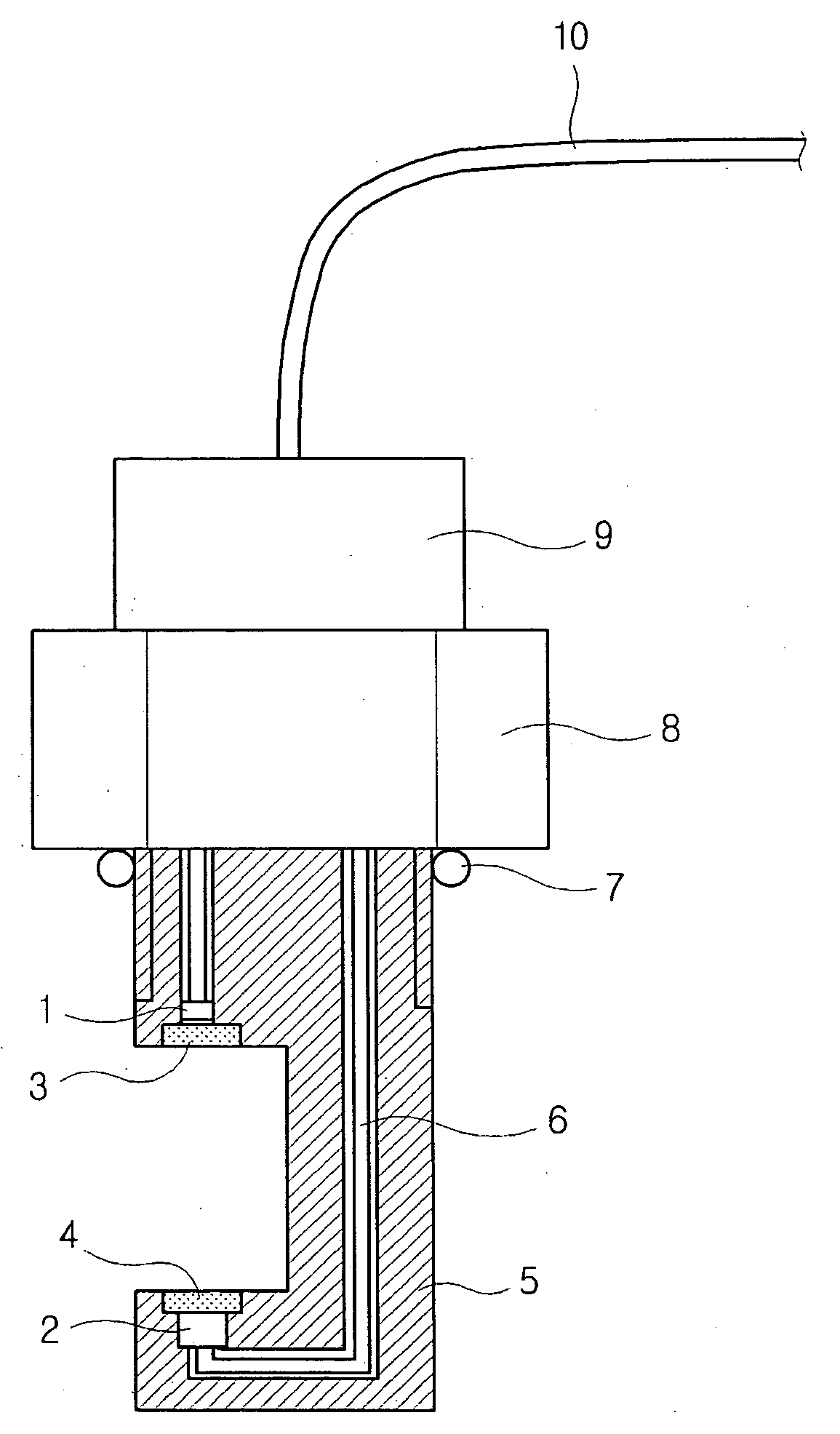
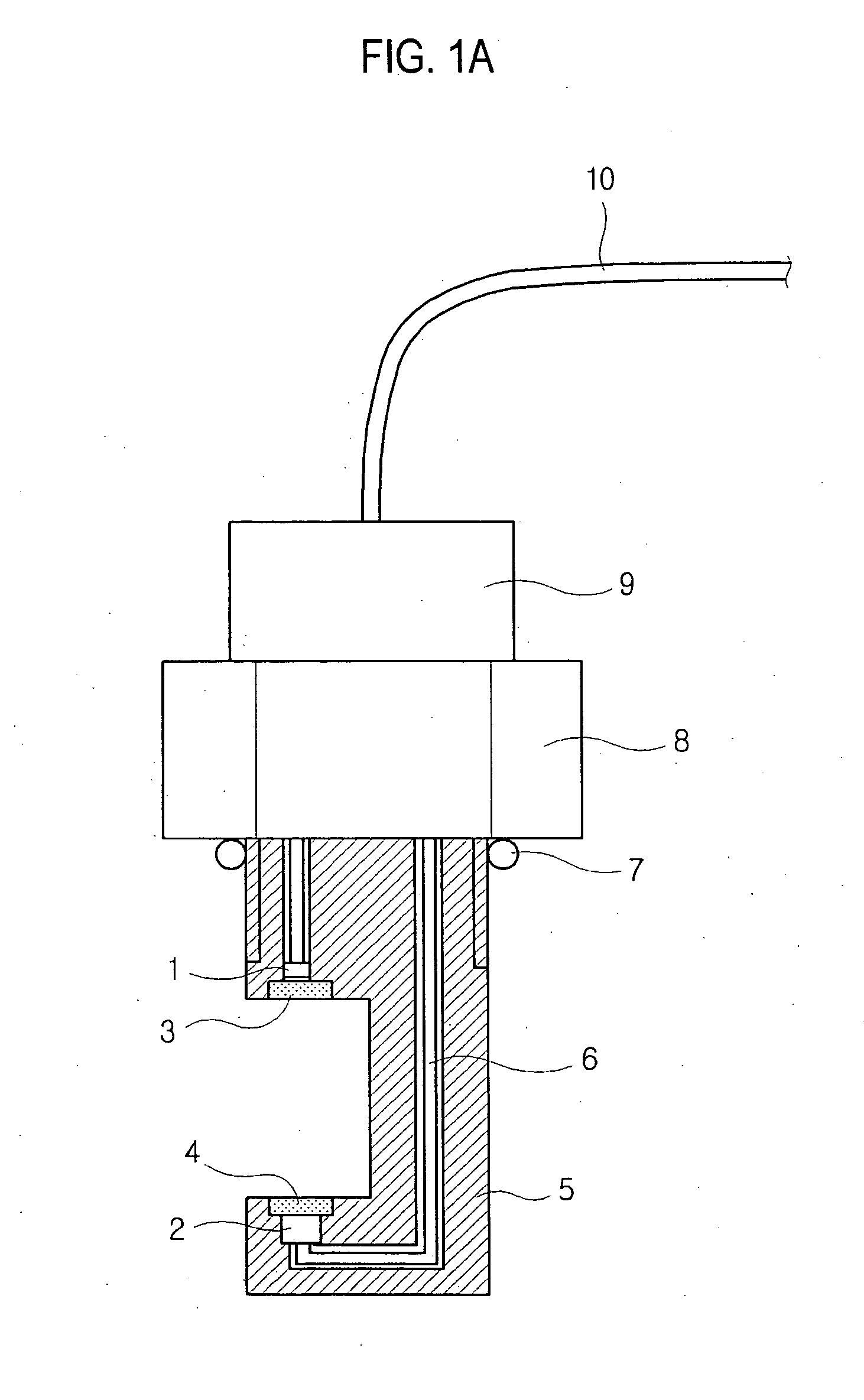
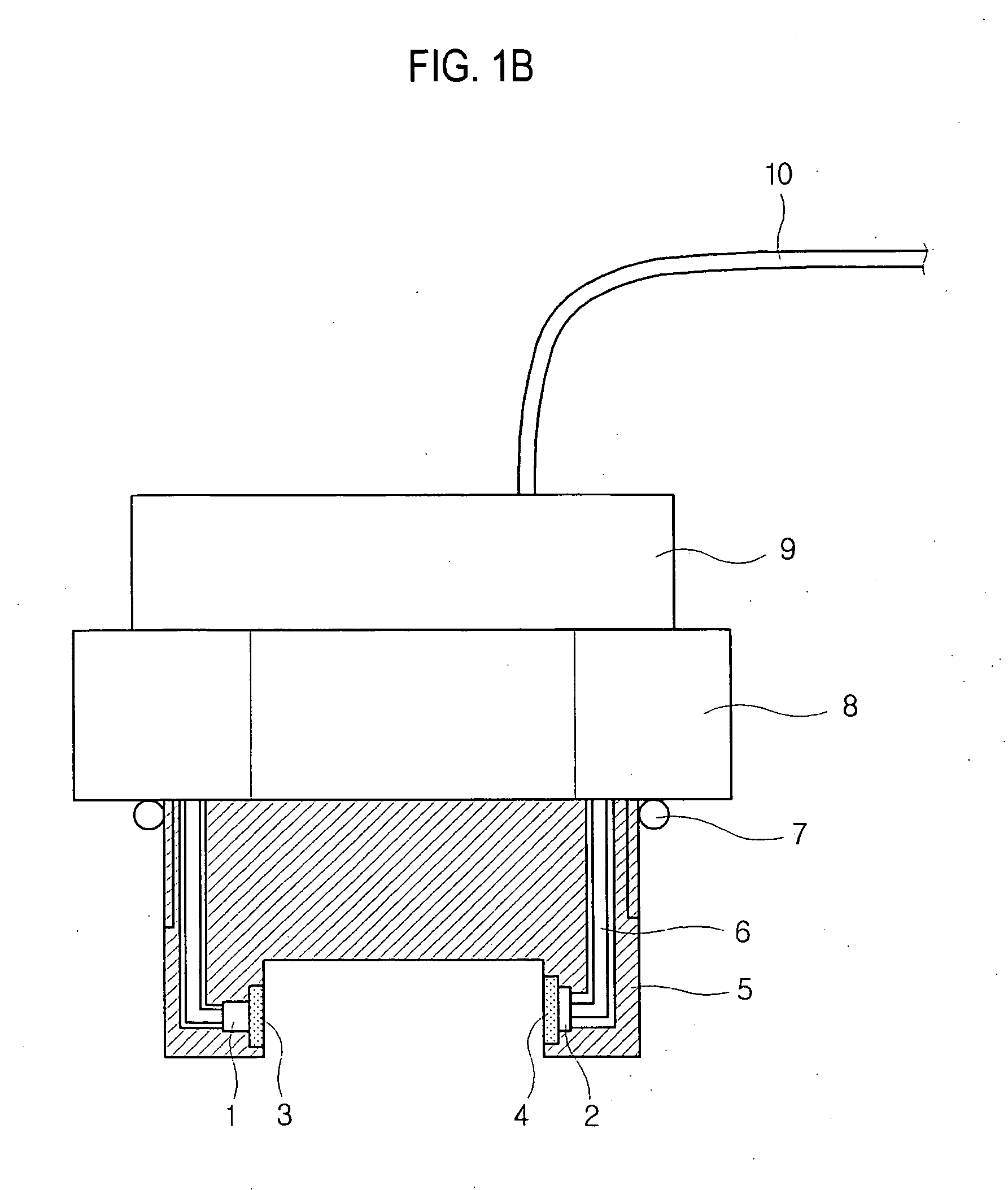
[0042]FIGS. 1A and 1B illustrate two exemplary apparatuses for monitoring oil deterioration according to the embodiments of the present invention. FIG. 2 shows the monitoring apparatus mounted inside of an oil tank.

[0043]The apparatus of the present invention for monitoring oil deterioration in real time includes a light source unit and a color sensing unit. An oil to be monitored is placed between the light source unit and the color sensing unit. In the embodiment of FIG. 1A, the light source unit and the color sensing unit are disposed vertically against the wall of an oil container. In the embodiment of FIG. 1B, the light source unit and the color sensing unit are disposed horizontally against the wall of an oil container.

[0044]The light source unit includes a light emitter 1 and...


PUM


Abstract

There is provided a method and apparatus for monitoring oil deterioration in real time. The method includes the steps of radiating light into an oil medium and measuring light intensities at red, green and blue wavelength ranges of the light after passing through a certain thickness of the oil. A ratio of the light intensity at the red wavelength range to the light intensity at the green wavelength range is computed by using the measured light intensities. These steps are repeated to monitor a change in the above ratio value in real time of oil use. The apparatus includes a light source means for radiating light into an oil medium, a color sensing means for measuring light intensities at red, green and blue wavelength ranges of the light that has passed through a certain thickness of the oil, and a control means for computing and monitoring a ratio of the light intensity at the red wavelength range to the light intensity at the green wavelength range, using the light intensities measured by the color sensing means.

Description

[0001]The present application claims priority from Korean Patent Application No. 10-2006-0070869 filed on Jul. 27, 2006, the entire subject matter of which is incorporated herein by reference.BACKGROUND OF THE INVENTION[0002]1. Field of the Invention[0003]The present invention generally relates to a method and apparatus for monitoring oil conditions in real time, and more particularly to a method and apparatus for monitoring oil by using certain parameters in order to determine an optimal timing for oil change.[0004]2. Background of the Invention[0005]As is commonly known, proper lubrication extends the service life of machines. When the machines are operated, a lubricant continues to be exposed to high temperatures, high speed, stress or loads, and an oxidizing environment. Thus, the lubricant tends to deteriorate and lose its lubricating effect. If the deteriorated lubricant continues to be used, then the heat becomes intensified and the lubricant is deteriorated at a faster pace....

Claims


Application Information

Patent Timeline
IPC IPC(8): G01N33/28
CPCG01N21/314G01N21/5907G01N21/8507G01N33/2888G01N21/85G01N21/94G01N21/00
Inventor KONG, HOSUNGYOON, EUI SUNGHAN, HUNG GUMARKOVA, LYUBOVSEMENYUK, MIKHAILMAKARENKO, VLADIMIR
Owner KOREA INST OF SCI & TECH
Why Eureka
Try Eureka