Fluid Control Device

Inactive Publication Date: 2008-02-07
ASAHI YUKIZAI KOGYO CO LTD
View PDF7 Cites 29 Cited by
  • Summary
  • Abstract
  • Description
  • Claims
  • Application Information

AI Technical Summary

Benefits of technology

[0038] (3) By the parts for performing the fluid control being configured separated into two arranged in the valve module and electrical component module and the wiring connected detachably through connectors, it is possible to set them inside the semiconductor production system etc., easily connect the pipes and wiring, and perform the work in a short time. Detachment is also easy and the layout of the modules can be easily changed.
[0039] (4) By using the pressure control valve of the configuration of the present invention, stable fluid pressure control becomes possible by a compact structure. Further, since it constantly exhausts compressed air in the cavity, the permeating corrosive gas will not corrode the spring, so measures such as coating of the spring become unnecessary, and the valve can be produced inexpensively.
[0040] (5) By using the constant flow valve of the configuration of the present invention, stable flow rate control becomes possible by a compact structure.

Problems solved by technology

There were therefore the problems that the work was complicated and required time and that the piping and wiring were troublesome and mistakes easily occurred.
Further, when connecting pipes, tubes, engagement parts, etc. were used for the connections, so pressure loss ended up occurring at the connection parts.
There was therefore the problem that this pressure loss affected the flowmeter side resulting in larger measurement error of the flow rate and making accurate control by the flow rate difficult.
Further, the flow measuring device 104 used parts liable to corrode, so there was the problem that when using a corrosive fluid as the fluid, the permeation of corrosive gas led to corrosion of the parts in the flow measuring device 104.
Further, in the conventional flow rate control module 106, when using a corrosive fluid for the fluid, if the permeated corrosive gas filled the inside of the flow rate control module 106, the controller 112 or the driver 111 would end up being corroded, the operations of fl

Method used


Image

  • Fluid Control Device
  • Fluid Control Device
  • Fluid Control Device

Examples


first embodiment

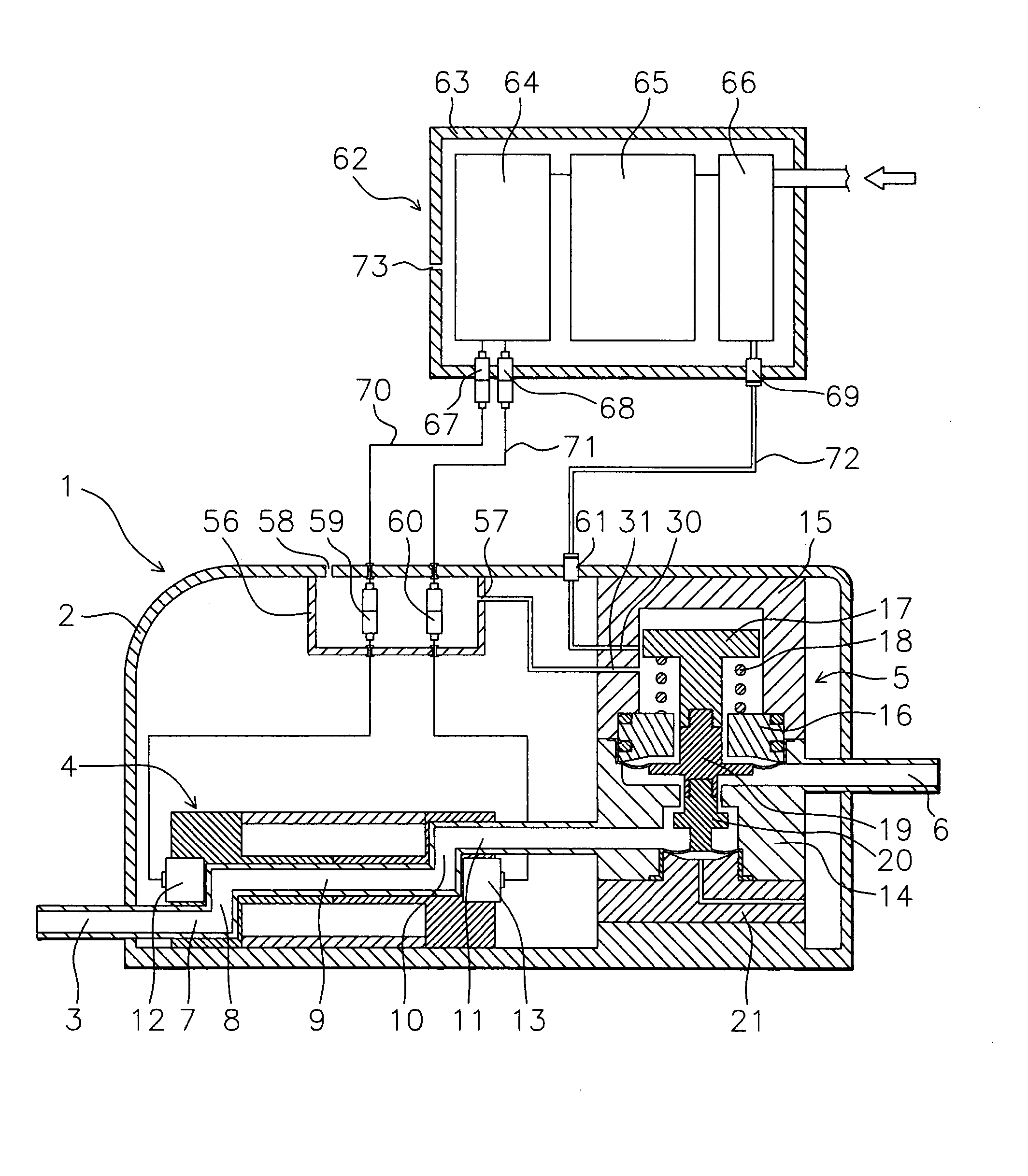
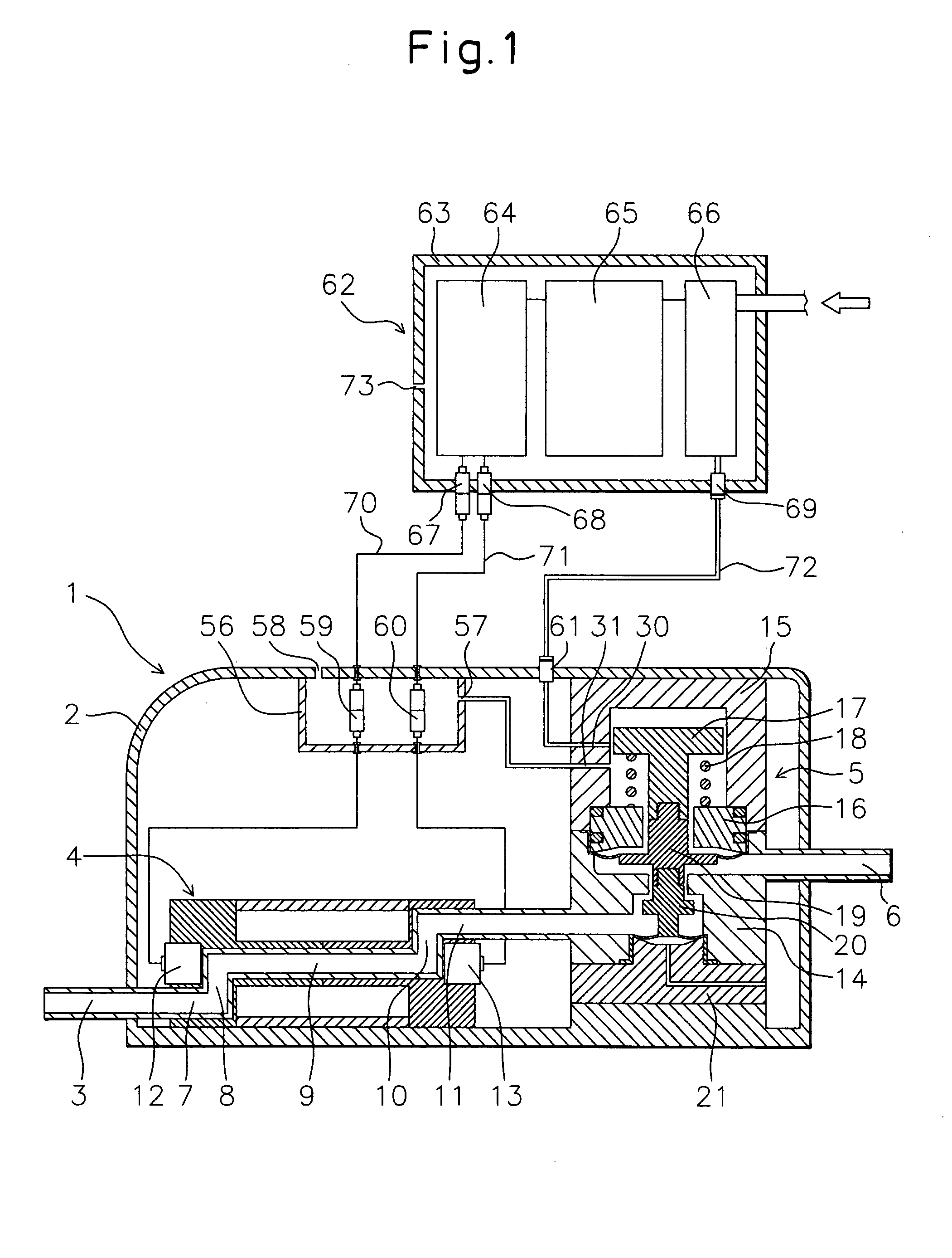
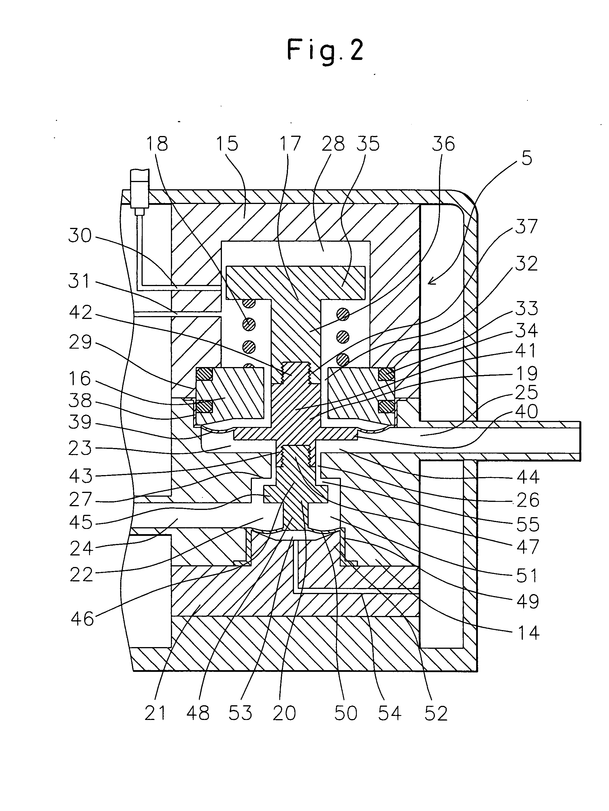
[0055] Below, a fluid control system of the present invention will be explained based on FIG. 1 and FIG. 2.

[0056]1 is a valve module. The valve module 1 is formed from a casing 2, fluid inlet 3, flowmeter sensor part 4, pressure control valve 5, and fluid outlet 6. Each is configured as follows:

[0057]2 is a PVDF casing. In the casing 2, the flowmeter sensor part 4 and pressure control valve 5 are fastened by bolts and nuts (not shown) to the bottom of the casing 2. The fluid inlet 3, flowmeter sensor part 4, pressure control valve 5, and fluid outlet 6 are arranged in the state successively connected in that order. Further, the casing 2 is provided with a later explained connector box 56. The connector box 56 is formed so that inert gas or air is supplied from an intake hole 57 and exhausted from an exhaust hole 58. Note that the flowmeter sensor part 4 and the pressure control valve 5 may also be reversed in order.

[0058]3 is a PTFE fluid inlet. The fluid inlet 3 is communicated w...

second embodiment

[0093] Below, a fluid control system of the present invention will be explained based on FIG. 3 and FIG. 4.

[0094]74 is a flowmeter sensor part arranged inside the casing 76 of the valve module 75. The flowmeter sensor part 74 has an inlet channel 77, a vortex generator 78 generating a Karman vortex provided vertically inside the inlet channel 77, and an outlet channel 79 provided in a straight channel 80. The ultrasonic oscillators 81, 82 are arranged facing each other at positions at the side walls of the straight channel 80 at the downstream side of the vortex generator 78 perpendicularly intersecting the channel axial direction. The ultrasonic oscillators 81, 82 are covered by a fluororesin. The wires extending from the oscillators 81, 82 are connected to connectors 84, 85 inside the connector box 83. In the same way as the first embodiment, the connector box 83 is formed so that compressed inert gas or air is supplied from its own intake hole and is exhausted from an exhaust hol...

third embodiment

[0101] Below, a fluid control system of the present invention will be explained based on FIG. 5 to FIG. 7.

[0102]201 is a valve module. The valve module 201 is formed from a casing 202, fluid inlet 203, flowmeter sensor part 204, constant flow valve 205, and fluid outlet 206. These are configured as explained above.

[0103]202 is a PVDF casing. In the casing 202, the flowmeter sensor part 204 and constant flow valve 205 are fastened by bolts and nuts (not shown) to the bottom of the casing 202. The fluid inlet 203, flowmeter sensor part 204, constant flow valve 205, and fluid outlet 206 are arranged in the state successively connected in that order. Further, the casing 202 is provided with a later explained connector box 274. The connector box 274 is formed so that inert gas or air is supplied from an intake hole 275 and exhausted from an exhaust hole 276. Note that the flowmeter sensor part 204 and the constant flow valve 205 may also be reversed in order.

[0104]203 is a PTFE fluid i...


PUM


Abstract

A fluid control system with easy installation in a semiconductor production system etc. and pipe and wiring connections, with reduced pressure loss due to pipe connections, with easy change of arrangement of modules, free from corrosion even using a corrosive fluid for the fluid, and enabling control of the flow rate even with pulsation of the inflowing fluid is provided. The fluid control system of the present invention is characterized by having a flowmeter sensor part having an ultrasonic oscillator generating an ultrasonic wave in a fluid and an ultrasonic oscillator receiving the ultrasonic wave generated from the ultrasonic oscillator and outputting a signal to a flowmeter amplifier and a control valve controlling the state of flow of fluid to a predetermined state by a working pressure, wherein the flowmeter sensor part and the control valve are arranged inside a casing having a fluid inlet and a fluid outlet.

Description

TECHNICAL FIELD [0001] The present invention relates to a fluid control system used in a fluid transport pipe where control of the fluid is required. More particularly, it mainly relates to a fluid control system with easy installation in a semiconductor production system etc. and pipe and wiring connections and with no concern over corrosion even if using a corrosive fluid for the fluid. BACKGROUND ART [0002] In the past, as one step in the process of production of a semiconductor, use has been made of wet etching using a washing solution comprised of fluoric acid or another chemical diluted by pure water to etch the wafer surface. It is considered that the concentration of the washing solution in this wet etching has to be managed with a high precision. In recent years, the method of managing the concentration of the washing solution by the ratio of flow rates of the pure water and chemical has become the mainstream. For this reason, a fluid control system managing the flow rates ...

Claims


Application Information

Patent Timeline
IPC IPC(8): G05D7/06
CPCF16K41/12G05D7/0635G01F1/66Y10T137/2196G05D7/06
Inventor YOSHINO, KENRO
Owner ASAHI YUKIZAI KOGYO CO LTD
Why Eureka
Try Eureka