Manufacturing Process, Such as Three-Dimensional Printing, Including Solvent Vapor Filming and the Like

a manufacturing process and three-dimensional printing technology, applied in the field of manufacturing process, can solve the problems of increased difficulty in dispense of organic solvents from printheads, increased difficulty in resolidification, so as to achieve more control over the porosity of the resolidified structure and small volume

Inactive Publication Date: 2008-02-07
MASSACHUSETTS INST OF TECH
View PDF99 Cites 35 Cited by
  • Summary
  • Abstract
  • Description
  • Claims
  • Application Information

AI Technical Summary

Benefits of technology

[0063] In the practice of the present invention, the deposition of the aqueous binder liquid can be done at a saturation parameter as small as 10% to 20%. This range is substantially smaller than what is used in most three-dimensional printing, and this is useful in improving the dimensional resolution of the final product.
[0066] It is believed, although it is intended not to be restricted to this explanation, that the structure of the water-soluble particles, together with any binder substance that may have been dissolved in the binder liquid (if any such binder substance was used), forms a structure which will keep the organic-solvent-soluble particles in position while those particles are not yet joined to each other. Similarly, it is believed that if any insoluble particles are present, this structure will keep the insoluble particles in position during this stage of manufacturing.
[0068] For relatively large parts, where the internal regions are relatively distant from external surfaces, it maybe helpful to use a vacuum container in which the organic solvent is introduced and achieves partial pressure, instantly filling interior regions, to eliminate or reduce any propensity for surface capillary stress cracks, which can result in a saturated air environment where migration of solvent vapor by diffusion is retarded.
[0070] It is further believed that when the particles of organic-solvent-soluble substance become dissolved or at least softened, they deform, flow or spread and it is believed that the pre-existing structure formed by the water-based binder liquid provides a surface / structure upon which the organic-solvent-soluble particles can spread when they become soft and will thereby help the organic-solvent-soluble particles find each other and coalesce. It is believed that the dissolved or softened particles of organic-solvent-soluble substance then contact and at least somewhat merge with other particles of the same substance, thereby forming a connected film structure of the organic-solvent-soluble substance.
[0077] It has been found that particles of sodium chloride have an ability to absorb a certain amount of moisture before they actually begin to form necks which would join particles to each other. This property may be of some help in limiting the spread of aqueous liquid in the powder bed. The rate of dissolution of sodium chloride in water could be described as moderate among the various substances tried.
[0079] It is thus likely that the lactose particles as originally supplied in the powder may still have a significant presence at the time the solvent-vapor-softened polymer flows to attain its final state. For example, the structure after aqueous binding may comprise lactose particles joined to each other by necks which are made primarily of one of the other, more water-soluble sugars. Thus the lactose particles as originally supplied in the powder may significantly determine the size and size distribution of the pores which exist in the final product. Achieving this situation may be helped if the amount of relatively quickly-dissolving sugar, which is intended to be in the necks, is somewhat smaller than the amount of lactose (because if the particles are to retain a prominent shape, the necks have to have smaller volume than the particles). It is believed that this gives more control over the porosity of the resolidified structure than would be available from dissolution / resolidification with just a single substance in the powder bed.

Problems solved by technology

Organic solvents have tended to be more difficult to dispense from printheads than aqueous solvents, because of their combination of low viscosity and low surface tension.
Chloroform in particular, even when it has been successfully dispensed from a printhead, has exhibited further difficulties which relate to how sharp a feature can be created during three-dimensional printing.
First of all, chloroform's unusually small surface tension and viscosity have given it extra tendency to spread by capillary action in a powder bed.
Additionally, there has been a difficulty associated with the time scale at which chloroform evaporates.
If the solvent evaporates before there has been sufficient time for dissolution to occur, little binding can be achieved.
This in turn has degraded dimensional resolution of printed features and has made it more difficult to remove unbound powder.
For example, bleeding has resulted in powder particles being stuck to the printed region which are not really desired to be stuck to the printed region.
Other difficulties associated with the use of chloroform and similar solvents in 3DP have been the exposure of nearby components of the 3DP machine to the vapor of a solvent which is aggressive against many materials, and the exposure of the entire binder liquid supply system to liquid chloroform, and the handling of chloroform vapor, which is toxic.
Another issue in 3DP has been that 3DP tends to require adjustment of printing parameters to values which are unique to a particular powder and a particular solvent or binder liquid being used.
If there are many powders or solvents / binders of interest, then significant effort can be required to determine specific printing parameters, i.e. it can be hard to respond quickly to a change in the formulation.
However, those structures were made by dispensing liquid chloroform from a printhead, which resulted in problems of bleeding of dispensed liquid in the powder bed, and so those articles did not have the dimensional resolution of the articles of the current invention.
However, this has not extended to three-dimensional printing, nor has it involved leaching of a porogen for creation and control of pores.

Method used


Image

  • Manufacturing Process, Such as Three-Dimensional Printing, Including Solvent Vapor Filming and the Like
  • Manufacturing Process, Such as Three-Dimensional Printing, Including Solvent Vapor Filming and the Like
  • Manufacturing Process, Such as Three-Dimensional Printing, Including Solvent Vapor Filming and the Like

Examples


example 1

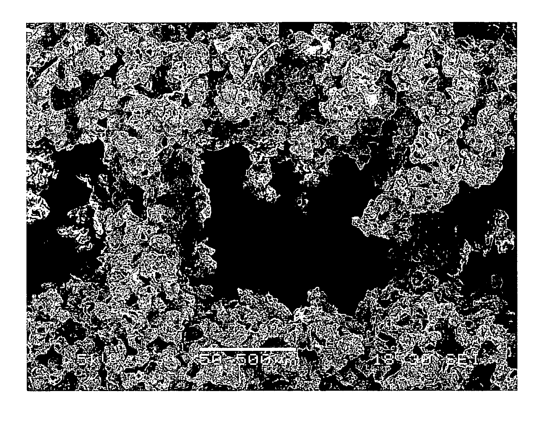
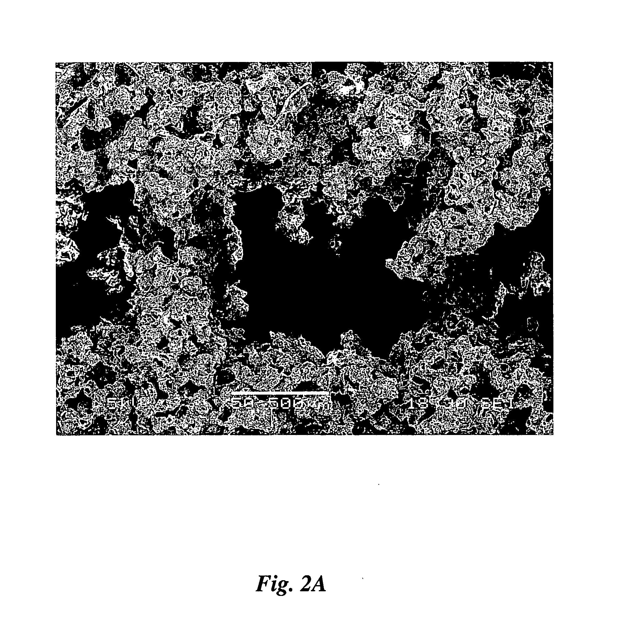
[0086] This Example compares the microstructure of polymer structures which were 3D-printed using the water printing solvent vapor fusing of the present invention against the microstructure of polymer structures which were 3D-printed using conventional dispensing of liquid chloroform onto a powder bed operating using the dissolution / resolidification mechanism. Both powderbeds contained a water-soluble porogen for later leaching out as an aid to creating porosity in the finished biostructure.

[0087]FIGS. 4A, 4B and 4C illustrate the microstructure of the structure made by conventional 3DP with dispensed liquid chloroform. The powder used in this case was 80:20 NaCl:PCL, magnifications are ×150, ×250 and ×650, respectively.

[0088] There is some basic polymeric structure, which has the form of a film 432 (FIG. 4B) which is somewhat randomly crinkled and perforated but is somewhat continuous. This basic polymeric structure is believed to come from polymer material which dissolved comple...

example 2

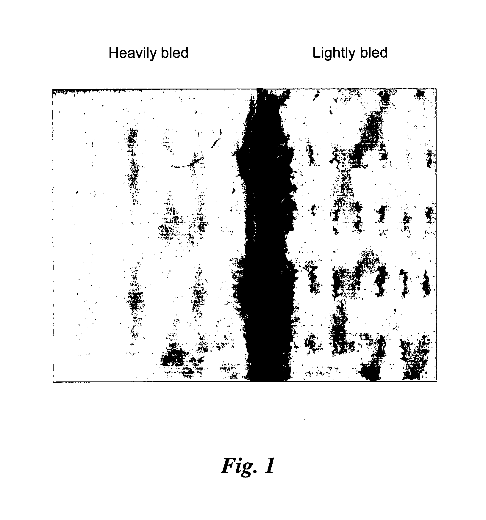
[0093] This example compares the macrostructure of polymer structures which were 3D-printed using the water printing solvent vapor fusing of the present invention against the macrostructure of polymer structures which were 3D-printed using conventional dispensing of liquid chloroform onto a powder bed operating using the dissolution / resolidification mechanism. Both powder beds contained a water-soluble porogen for later leaching out as an aid to creating porosity in the finished biostructure.

[0094]FIG. 10 shows a face or top view of a structure. Actually, the two images in that figure are of not exactly the same part of a complicated structure. The sample on the right, printed by a process of a present invention, illustrates a sort of a screen structure. The sample on the left, printed by conventional dispensing of liquid chloroform, illustrates a structure which is sort of a collection of posts. Nevertheless, the size scales are the same and so there is validity in comparing the f...

example 3

[0096] The next example, shown in FIG. 12, compares printing onto the same powder bed composition with a pure water binder liquid (right) and printing with a binder liquid that is a solution of sucrose in water (left). It is believed that the structure resulting from the sucrose solution printing is better held together, and the structure with pure water is more flaky. It is believed that the presence of the sucrose provides binding with less dependence on dissolution taking place during the 3DP process itself, and results in somewhat better filling of spaces between particles and attachment of particles to each other.

[0097] It is believed that the sucrose solution has different wetting characteristics from plain water. It is believed that the sucrose solution causes more powder rearrangement (powder particles pulling closer to each other during the time when they are wet), which means that the primitive features thus formed pull slightly away from the bulk powder, which results in...


PUM

PropertyMeasurementUnit
sizeaaaaaaaaaa
porosityaaaaaaaaaa
sizeaaaaaaaaaa

Abstract

Methods of manufacturing an article use three-dimensional printing for a portion of the manufacturing. Three-dimensionally printing is conducted onto a powder bed which contains both organic-solvent-soluble, water-insoluble particles and water soluble, organic-solvent-insoluble particles. The water-soluble particles which may be selected for properties such as size and may include more than one substance. The organic-solvent-insoluble particles may further include at least one substantially insoluble substance such as a member of the calcium phosphate family. Printing may be done using an aqueous binder liquid. After removal of unbound powder, the preform may be exposed to the vapor of an organic solvent which causes the particles of organic-soluble-polymer to fuse to each other. This may further be followed by dissolving out the water-soluble particles, if such particles were present in the powder. Solvent vapor fusing together with the use of porogen particles may also be used in manufacturing methods other than 3DP. Rather than using organic solvent, heat responsive particles can be used, and can be filmed by elevated temperatures. Articles that may be produced by the described methods exhibit features such as a high porosity and an ability to undergo large deformations without breaking, and by at least partial springback from such deformation. The springback may be substantially instantaneous or may be time-dependent involving a time period of at least several seconds.

Description

RELATED DOCUMENTS [0001] This application claims priority to and benefit of the filing date of U.S. Provisional Patent Application 60 / 570,412, filed on May 12, 2004, in the names of J. Serdy et al, entitled MANUFACTURING PROCESS, SUCH AS THREE-DIMENSIONAL PRINTING, INCLUDING SOLVENT VAPOR FUSING, which is incorporated fully herein by reference.BRIEF DESCRIPTION OF THE FIGURES OF THE DRAWING [0002]FIG. 1 is a digital image showing a heavily bled three dimensional printing structure on the left and a lightly bled structure on the right; [0003]FIG. 2A is a digital image of a scanning electromicrograph of an article made by a vapor film forming method of an invention hereof having a powder mixture of 80% sugar and 20% PCL at a magnification of ×50. [0004]FIG. 2B is a digital image of the article shown in FIG. 2A, at a magnification of ×160. [0005]FIG. 2C is a digital image of the article shown in FIG. 2A, at a magnification of ×900. [0006]FIG. 3A is a digital image of a scanning electro...

Claims


Application Information

Patent Timeline
Patent Type & Authority Applications(United States)
IPC IPC(8): G03C1/00A61F2/00A61F2/02A61F2/28A61F2/30
CPCA61F2/28Y10T428/24273A61F2002/30224A61F2002/30225A61F2002/30785A61F2002/30985A61F2210/0004A61F2230/0069A61F2310/00293A61F2310/00353A61L27/54A61L27/56A61L2300/412A61L2300/434A61L2300/602Y10T428/15A61F2002/30062Y10T428/31504B33Y70/00B33Y10/00B33Y80/00
Inventor SERDY, JAMES G.SACHS, EMANUEL M.
Owner MASSACHUSETTS INST OF TECH
Why Eureka
Try Eureka