
Laser cut intraluminal medical devices

a technology of medical devices and laser beams, applied in the direction of prosthesis, manufacturing tools, blood vessels, etc., can solve the problems of compromising the physical properties of the materials comprising the stent, and achieve the effects of reducing or ideally eliminating the effects of moisture and oxygen, reducing the number of laser beams, and maintaining the consistency of laser beams

Inactive Publication Date: 2008-02-07
DAVE VIPUL BHUPENDRA
View PDF6 Cites 26 Cited by
  • Summary
  • Abstract
  • Description
  • Claims
  • Application Information

AI Technical Summary

Benefits of technology

"The invention provides a way to make a bioabsorbable stent or device that can be implanted in a patient's body. The device is made from a precursor sheet or tube of material that is laser cut into the desired shape. The laser cutting is done in an inert gas atmosphere to ensure precise geometry and pattern without compromising the strength of the device. The materials used can be produced from conventional methods and the desired pattern can be formed by a mask during laser cutting. The laser processing unit can include a coordinated multi-motion unit or a beam homogenizer to achieve the desired pattern. The invention allows for the creation of stents or devices with various strengths and flexibilities to better meet different medical needs."

Problems solved by technology

Processing at such conditions tends to compromise the physical properties of the materials comprising the stent.
None of the various art described combines techniques to provide a bioabsorbable intraluminal medical device, such as a stent, that is formed using mask projection laser cutting techniques to provide an intraluminal device or stent of desired geometries or patterns having increased drug delivery capacity and radiopacity while minimizing damage to the materials comprising the device or stent during processing.

Method used


Image

  • Laser cut intraluminal medical devices
  • Laser cut intraluminal medical devices
  • Laser cut intraluminal medical devices

Examples


Embodiment Construction

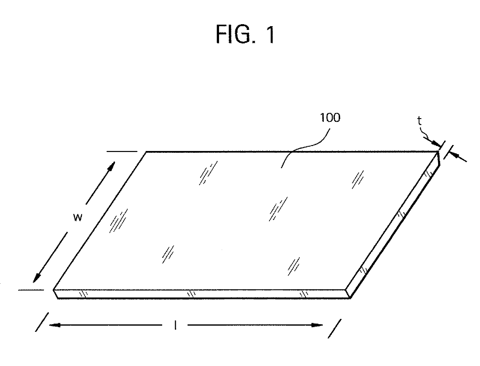
[0029]FIG. 1 illustrates a precursor sheet 100 of bioabsorbable material for forming an intraluminal medical device or stent according to the systems and methods of the invention. The precursor sheet 100 is produced from conventional compression molding or solvent casting techniques, for example, which are not further detailed herein as the artisan should readily appreciate how such precursor sheets 100 are formed using conventional techniques. The precursor sheet 100 is provided with length (l), width (w) and thickness (t) dimensions that may be varied from sheet to sheet in order to accommodate the formation of differently sized medical devices or stents. For example, where a longer anatomic vessel or passageway is the intended treatment site, then a longer length (l) dimension may be provided, or where increased radial strength is desirable, then a larger thickness (t) dimension may be provided. The precursor sheet 100 is comprised of bioabsorbable materials such as, for example,...


PUM

PropertyMeasurementUnit
inner diameteraaaaaaaaaa
lengthaaaaaaaaaa
lengthaaaaaaaaaa

Abstract

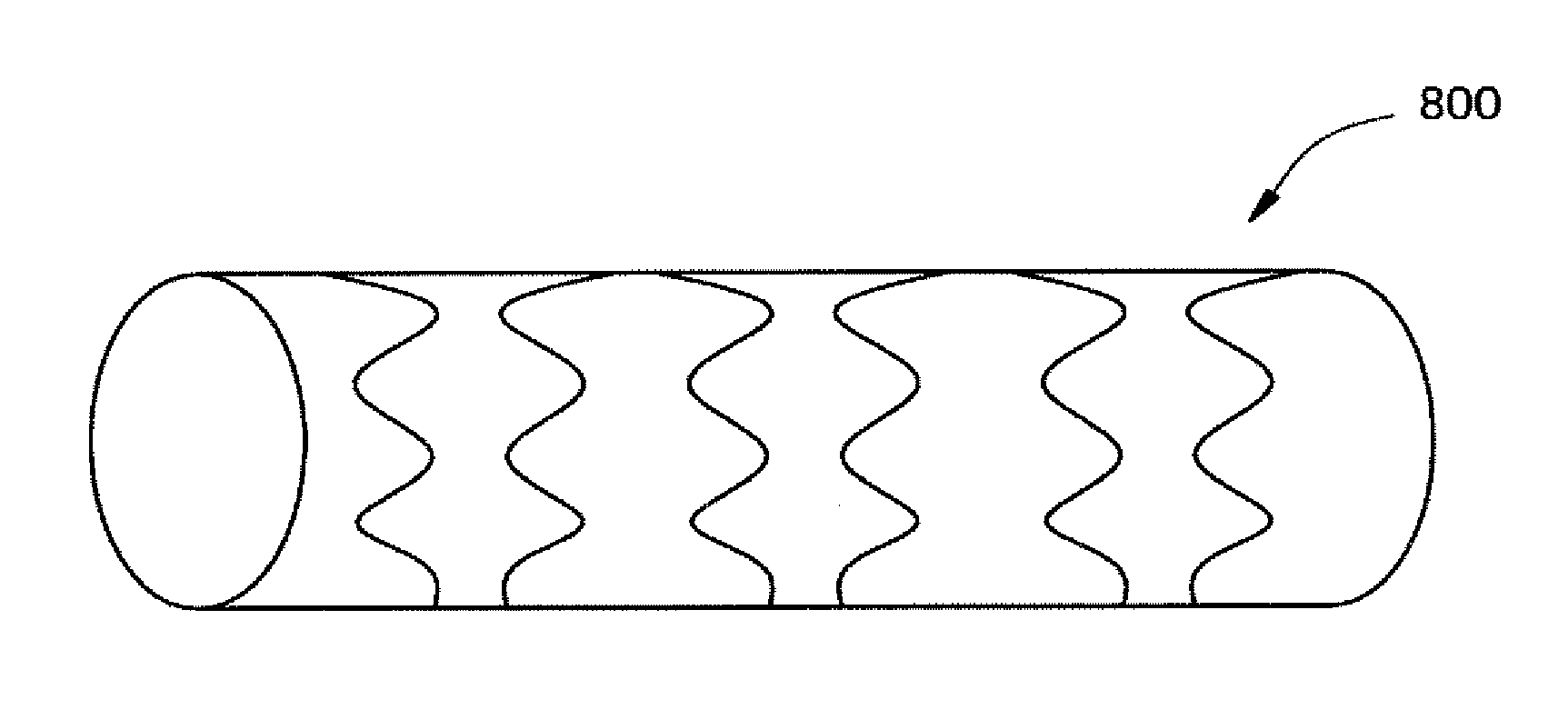
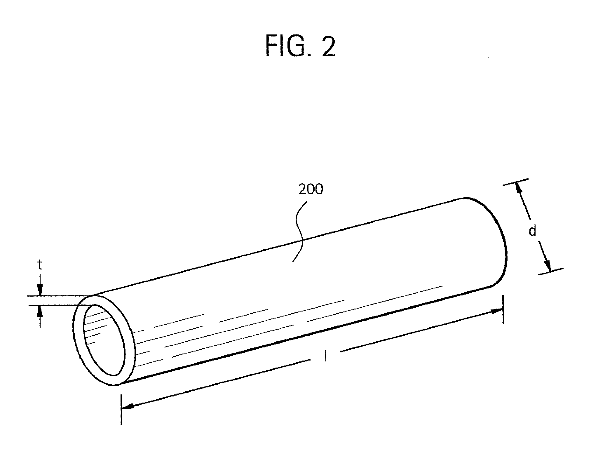
Laser cut bioabsorbable intraluminal devices or stents and methods for forming such an intraluminal device or stent. A precursor sheet or tube of bioabsorbable material is laser cut in the presence of an inert gas to form an intraluminal medical device or stent having a desired geometry or pattern. The device or stent may comprise a helical, or other shape, having the laser cut geometry or pattern imparted thereon. The device or stent may further comprise drugs or bio-active agents incorporated into or onto the device or stent in greater percentages than conventional devices or stents. Radiopaque materials may be incorporated into, or coated onto, the intraluminal device or stent. Precise geometries or patterns are simply and readily achievable using the laser cutting methods in the presence of an inert gas while minimizing damage to the precursor materials.

Description

CROSS REFERENCE TO RELATED APPLICATION [0001] This application is a divisional application of U.S. patent application Ser. No. 11 / 304,372 filed on Dec. 15, 2005, hereby incorporated by reference, to which this application claims priority under 35 U.S.C. §121.BACKGROUND OF THE INVENTION [0002] 1. Field of the Invention [0003] The invention generally relates to bioabsorbable intraluminal medical devices that are laser cut in an inert gas atmosphere to impart a desired geometry or pattern to the device. [0004] 2. Related Art [0005] Intraluminal endovascular medical devices, such as stents, are well-known. Such stents are often used for repairing blood vessels narrowed or occluded by disease, for example, or for use within other body passageways or ducts. Typically the stent is percutaneously routed to a treatment site and is expanded to maintain or restore the patency of the blood vessel or other passageway or duct within which the stent is emplaced. The stent may be a self-expanding s...

Claims


Application Information

Patent Timeline
Patent Type & Authority Applications(United States)
IPC IPC(8): A61F2/06
CPCB23K26/0639B23K26/0648B23K26/0656B23K2201/04B23K26/0823B23K26/123B23K26/4065B23K26/08B23K26/064B23K26/066B23K2101/04B23K2103/42B23K2103/50
Inventor DAVE, VIPUL BHUPENDRA
Owner DAVE VIPUL BHUPENDRA
Learn More