Versatile dehumidification process and apparatus

a dehumidification process and gas stream technology, applied in the direction of lighting and heating apparatus, heating types, separation processes, etc., can solve the problems of inability of dx technology to maintain the air introduced into the interior space at the correct humidity and temperature for maintaining comfort, and inability to independently control comfort parameters. , to achieve the effect of enhancing the flux through the osmotic wall, the effect of improving the overall flux

Inactive Publication Date: 2008-02-14
NANOCAP TECH
View PDF19 Cites 15 Cited by
  • Summary
  • Abstract
  • Description
  • Claims
  • Application Information

AI Technical Summary

Benefits of technology

[0024]Yet another advantage of the present invention is that a method and means for dehumidifying a gas stream is provided that can be used with unusual contours, such as the ducts of air handling equipment, the panels of cars, trucks, and ships as well as the walls of homes and office buildings, the clothing of hikers and of physicians in an operating room, and the bed linen of people who sleep in a humid environment. A membrane can be molded to the contour ...

Problems solved by technology

That makes it impossible to independently control comfort parameters, making the DX cycle less efficient, from an overall system perspective, than a technology that would allow independent control of sensible and latent heat.
In applications where the outside air has both high humidity and temperature and the functional use of the interior space generates high water vapor levels (e.g., populated convention halls, exercise rooms, school buildings, etc.), it may not be possible for the DX technology to maintain the air introduced into the interior space at the correct humidity and temperature for maintaining comfort.
The air delivered is cool but “muggy”, since further cooling to remove additional water would result in t...

Method used


Image

  • Versatile dehumidification process and apparatus
  • Versatile dehumidification process and apparatus
  • Versatile dehumidification process and apparatus

Examples


Embodiment Construction

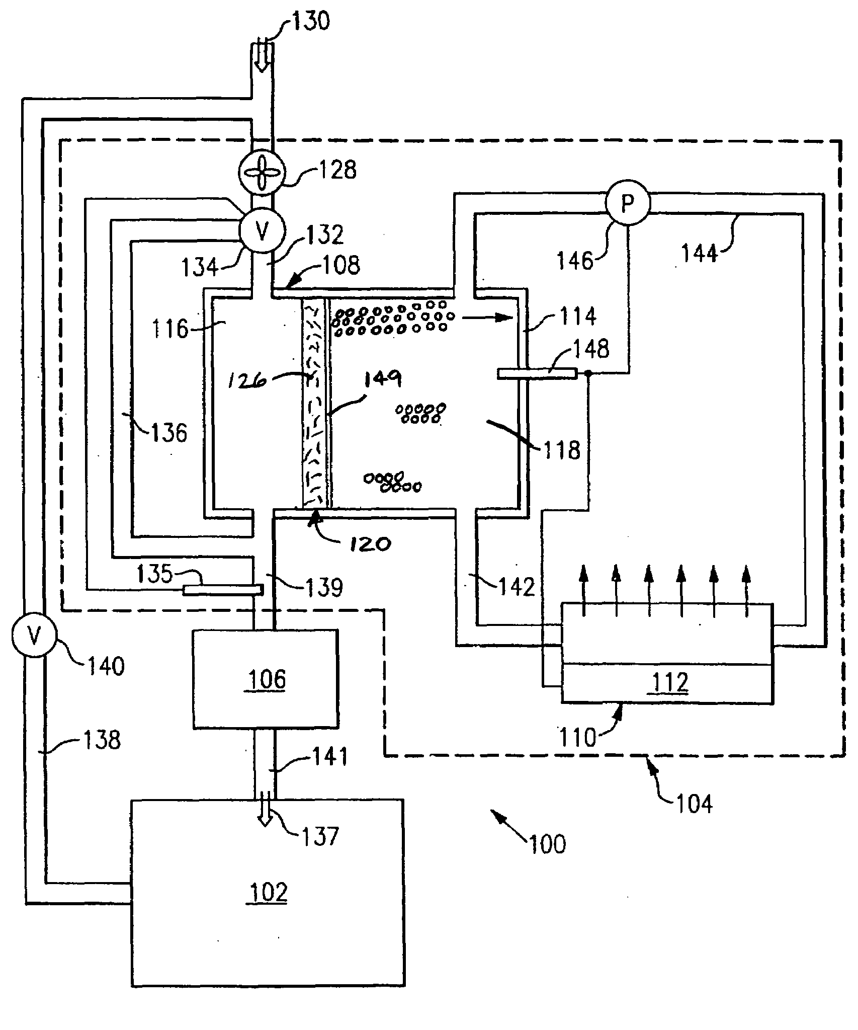
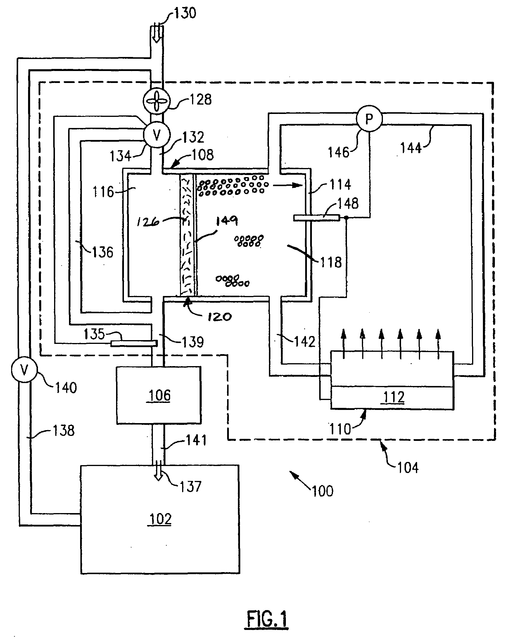
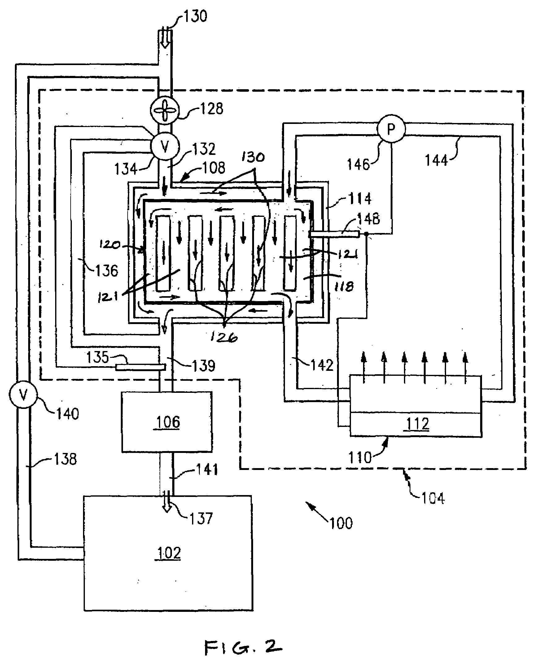
[0029]FIGS. 1 and 2 schematically depict an air conditioning system 100 for conditioning the gas (e.g., air) within an enclosed space 102. The system 100 includes dehumidification apparatus 104 (represented by the components within the dotted line) and cooling apparatus 106. The dehumidification apparatus includes a dehumidifier 108 and an evaporator 110. In this embodiment the evaporator includes an auxiliary heater 112. The dehumidifier 108 is schematically depicted as an enclosure 114 divided into an airflow compartment 116 and an osmotic fluid compartment 118. The compartment 118 contains an osmotic fluid, which is water with a solute dissolved therein. The compartments 116, 118 are separated by a semi-permeable osmotic wall 120 comprising an osmotic membrane 126 as will be described below.

[0030]Before providing a more detailed description of the properties and characteristics of the semi-permeable osmotic wall and osmotic fluid, and the interrelationships between them, it is he...


PUM


Abstract

A process and apparatus for dehumidifying a gas stream is provided. The process includes steps of: a) providing a semi-permeable wall having an osmotic membrane with a plurality of pores at least some of which are operably sized to permit capillary condensation, a first side, and a second side; b) placing an osmotic fluid in a compartment formed in part by the semi-permeable wall, wherein the second side of the osmotic membrane is exposed to the osmotic fluid; c) exposing the first side of the osmotic membrane to the gas stream to be dehumidified; and d) maintaining a sufficiently high water concentration gradient across the osmotic membrane during the dehumidification process to result in a flux of water through the osmotic membrane. The apparatus includes at least one semi-permeable osmotic wall, at least one gas stream compartment formed in part by the osmotic wall, and at least one osmotic fluid compartment formed in part by the osmotic wall. Each semi-permeable osmotic wall has an osmotic membrane with a first side and a second side. The first side of each osmotic membrane is exposed to the gas stream compartment, and the second side of each osmotic membrane is exposed to the osmotic fluid compartment.

Description

TECHNICAL FIELD[0001]This invention relates to processes and apparatus for conditioning a gas stream, such as air, and to the dehumidification of a gas stream in particular.BACKGROUND ART[0002]Conditioning of a gas stream, such as air, generally involves the removal or addition of moisture and the increase or decrease of temperature to make the gas stream suitable for its intended environment. For air conditioning in warm weather, this typically involves dehumidifying and cooling the air to comfortable levels.[0003]Current dehumidification technology is commonly based on the conventional, refrigerant vapor compression cycle (hereinafter referred to as DX technology) or on desiccant substrate capture technology (hereinafter referred to as DS technology). DX technology requires cooling humid supply air, such as the air within a room and / or outside air, to the water vapor condensation point, with external heat rejection on the compression side. This usually requires the supply air to b...

Claims


Application Information

Patent Timeline
IPC IPC(8): B01D53/22
CPCB01D53/229B01D53/268F24F2003/144F24F3/147F24F2003/1435F24F3/1417
Inventor KESTEN, ARTHUR S.BLECHNER, JACK N.
Owner NANOCAP TECH
Why Eureka
Try Eureka