Exhaust gas post treatment system

a post-treatment system and exhaust gas technology, applied in the direction of physical/chemical process catalysts, separation processes, filtration separation, etc., can solve the problems of nitrogen oxide reduction, difficult quantitative measurement of reduction agents, and use of scr catalyst active material vsub>2/sub>o/sub>5/sub>, so as to reduce engine power, reduce the effect of very fine particles and increase the counter pressure of exhaust gas

Active Publication Date: 2008-02-21
MAN NUTZFAHRZEUGE AG
View PDF9 Cites 27 Cited by
  • Summary
  • Abstract
  • Description
  • Claims
  • Application Information

AI Technical Summary

Benefits of technology

[0007]To minimize the very fine particles, not only in the power plant industry but also with vehicles, either so-called particle separators or particle filters are used. A typical arrangement having particle separators for use in vehicles is described, for example, in EP 1 072 765 A1. Such arrangements differ from those having particle filters in that the diameter of the channels of the particle separator are considerably greater than the diameter of the largest particle that is present, whereas with particle filters the diameter of the filter channels is in the range of the diameter of the particles. As a consequence of this difference, particle filters are subject to becoming clogged, which increases the exhaust gas counter pressure and reduces the engine power. An arrangeme...

Problems solved by technology

With internal combustion engines operated in vehicles the nitrogen oxide reduction with the aid of the SCR process is difficult for the reason that changing operating conditions exist that make the quantitative metering of the reduction agent difficult Although on the one hand as high a conversion of the nitrogen oxides as possible should be achieved, on the other hand care must be taken that there is no emission of unused ammonia.
The use of V2O5 as active material for the SCR catalyst can also pose a problem if the exhaust gas temperature at the SCR catalyst is greater than 650° C., because V2O5 then sublimates.
As a consequence of this difference, particle filters are subject to becoming clogged, which increases the exhaust gas counter pressure and reduces the engine power.
The drawback of this arrangement is that the nitrogen dioxide produced in the oxidation catalytic converter is essentially completely used up by the selective catalytic reduction in the SCR catalyst, in ...

Method used


Image

  • Exhaust gas post treatment system
  • Exhaust gas post treatment system
  • Exhaust gas post treatment system

Examples


Embodiment Construction

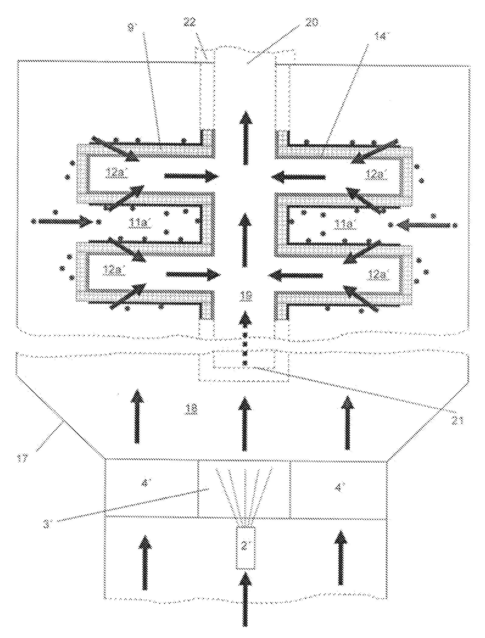
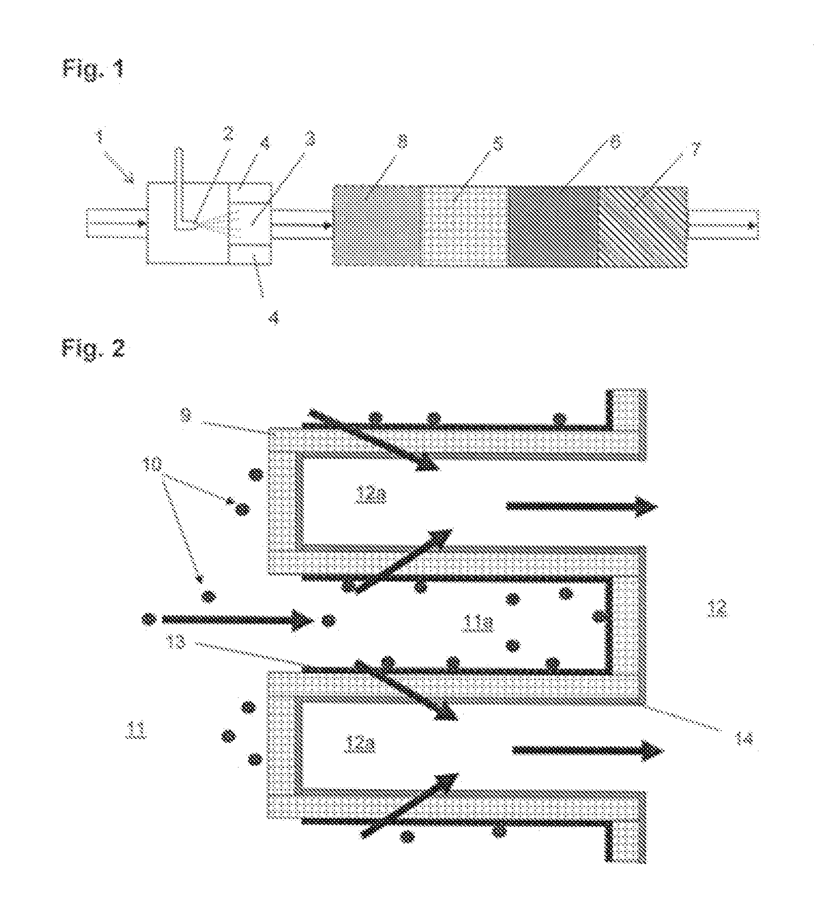
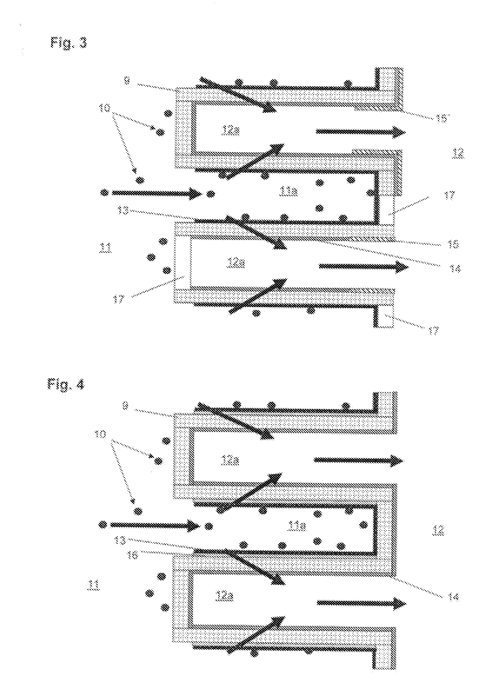
[0031]Referring now to the drawings in detail, an exhaust gas post treatment system for the selective catalytic reduction and for the reduction of solid particles in the exhaust gas of an internal combustion engine is schematically illustrated in FIG. 1. The exhaust gases, which are produced from an internal combustion engine (not illustrated) by the combustion processes, and which are symbolized by the arrows in FIG. 1, first pass into an exhaust gas preparation section 1, in which a reduction agent is added to the hot exhaust gas as close to the engine as possible. As is common with motor vehicles having SCR catalytic converters, the reduction agent is an aqueous urea solution; it is, of course, also conceivable to add urea in solid form, as this is already described in detail in the pertinent technical literature. It is furthermore possible to add ammonia as the reduction agent which is recovered at some other location, for example under more favorable thermal conditions, from a ...


PUM

PropertyMeasurementUnit
Flow rateaaaaaaaaaa

Abstract

An exhaust gas post treatment system for nitrogen oxide and particle reduction of internal combustion engines operated with excess air, comprising a particle filter disposed in the exhaust gas stream of the internal combustion engine. The particle filter is a surface-type particle filter or a deep bed filter, and is charged on an outlet side with an SCR-active catalyst material for reducing nitrogen oxides. Ammonia or an ammonia-releasing reduction agent is supplied to the exhaust gas stream upstream of the particle filter.

Description

[0001]The instant application should be granted the priority date of 16 Aug. 2006 the filing date of the corresponding Germany patent application DE 10 2006 038 288.9.BACKGROUND OF THE INVENTION[0002]The present invention relates to an exhaust gas post treatment system for internal combustion engines, such as diesel engines and gasoline engines having direct injection, that are operated with excess air.[0003]Limited exhaust gas components, which result during combustion processes and the permissible emissions of which are continuously being lowered, include, in addition to solid particles, nitrogen oxides. To minimize these exhaust gas components with internal combustion engines operated in motor vehicles, various methods are presently used. The reduction of the nitrogen oxides generally occurs with the aid of catalysts, and in oxygen-rich exhaust gas a reduction agent is additionally required in order to increase the selectivity and NOx conversions. These methods have become known ...

Claims


Application Information

Patent Timeline
IPC IPC(8): F01N3/035F01N3/20
CPCB01D39/06F01N13/0097B01D2239/0464B01D2239/0471B01D2239/0485B01D2239/0492F01N3/0231F01N3/035F01N3/0821F01N3/206F01N2250/02F01N2330/14F01N2330/60Y10S55/30Y02T10/24B01D39/2082Y02T10/12
Inventor DURING, ANDREAS
Owner MAN NUTZFAHRZEUGE AG
Why Eureka
Try Eureka