
Piping with heater and connecting method of the piping

a technology of connecting method and piping end, which is applied in the field of piping, can solve the problems of inapplicability of increasing the heater capacity, inconvenient and troublesome equipment and apparatuses, and inferior heat-retaining ability and defrosting ability at the piping end to those at the central portion of the piping, and achieves the effect of short time and reduced production cos

Inactive Publication Date: 2008-02-21
NISSAN DIESEL MOTOR CO +1
View PDF4 Cites 13 Cited by
  • Summary
  • Abstract
  • Description
  • Claims
  • Application Information

AI Technical Summary

Benefits of technology

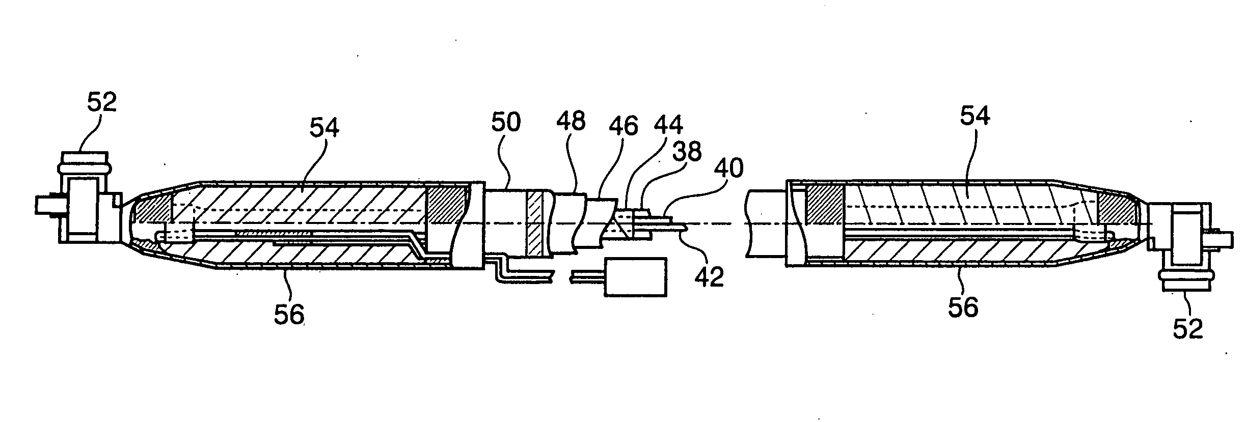
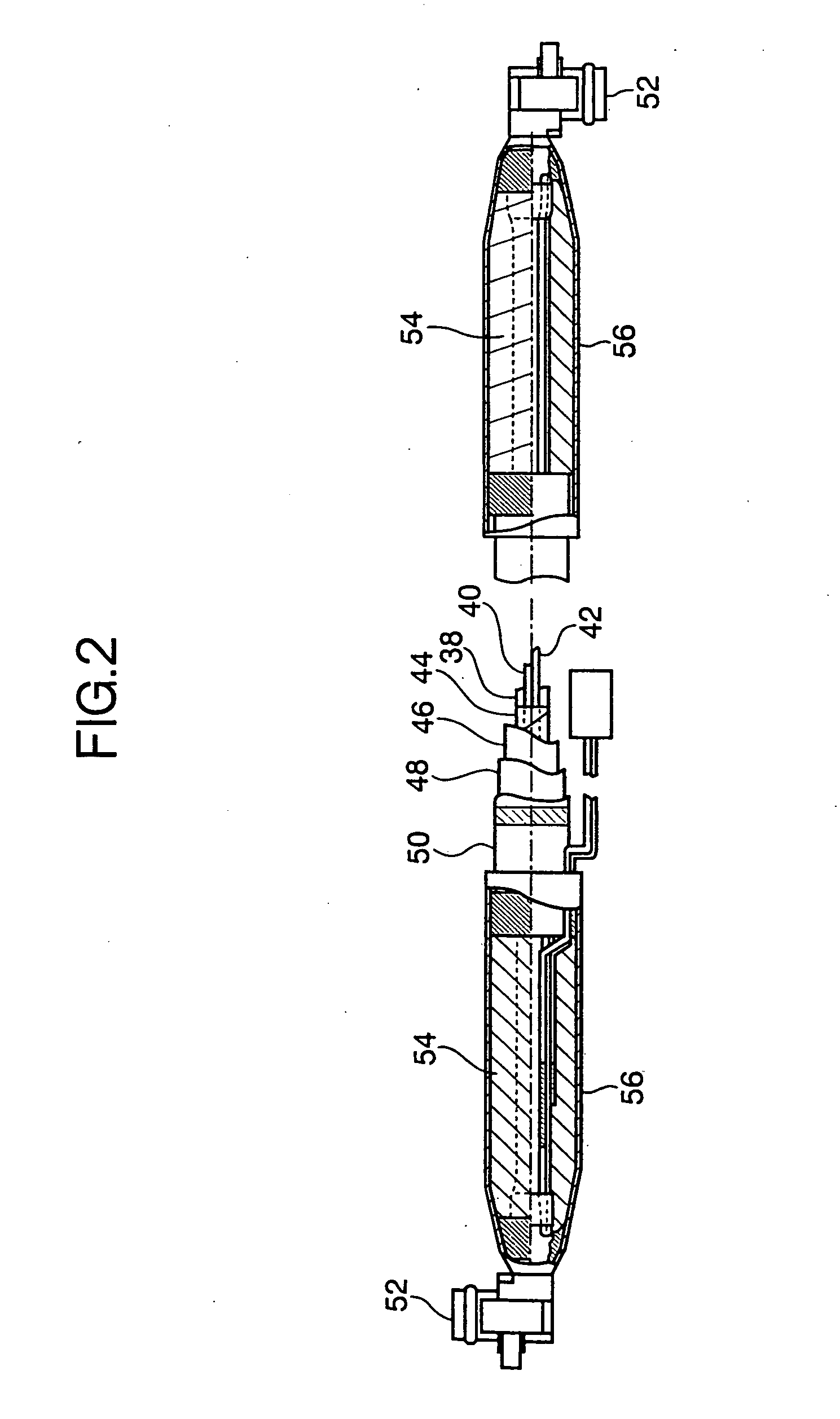
[0010]According to the described heater-attached piping, the end of the piping is configured to be heated by the predetermined length portion of the heater disposed along the substantially entire length of the piping through which fluid is transferred, which portion is formed in the multi-ply arrangement. Therefore, the amount of heat generating in that predetermined length portion when an identical electric current is supplied can be increased to bring about such advantages that the power consumption of the heater may be suppressed to the lowest possible limit, and the heat-retaining ability as well as defrosting ability at the piping end may be enhanced. At this stage, if the predetermined length of the heater to be formed into multi-ply arrangement is appropriately set in compliance with the heater capacity, supplied current and the like parameters, it is possible to exhibit substantially equal heat-retaining ability and defrosting ability over substantially the entire length of the heater-attached piping, and to effectively retain heat of the transferred fluid and to unfreeze the fluid to be transferred.
[0012]According to this connecting method, the heat-retaining layer located at the end is peeled off, portions of the piping and heater are exposed, the mating device is connected to the piping end and then, the exposed heater is formed into the multi-ply arrangement, the heat-retaining layer is disposed around the exposed piping and heater, and the periphery of the heat-retaining layer is coated with the heat-shrinkable tube. These series of operations are carried out in a predetermined sequence, thereby connecting the heater-attached piping to the mating device. Thus, it becomes easy to realize the heater-attached piping of the present invention using the existing heater-attached piping available from the market, and resultantly, curtailment of production cost and so on can be effected.
[0013]If the heat-equalizing layer is disposed, heat generated by the heater is substantially equally transmitted to the outer periphery of the piping through the heat-equalizing layer, the interior of the piping is substantially equally heated from its outer periphery, the temperature distribution of fluid to be transferred becomes substantially equal, and frozen fluid can be unfrozen in a short time.

Problems solved by technology

If there occurs condensation or freeze in an interior of the piping in, for example, water supply equipment, a gas analyzer or the like used in cold climates, such condensation or freeze will cause inconvenience and trouble with the equipment and apparatuses.
Therefore, heat generated by the cord-like heater is radiated to the periphery of the piping end, and the heat-retaining ability and the defrosting ability at the piping end are inferior to those at a central portion of the piping.
Nevertheless, in the case of a piping to be installed in a vehicle, since the capacities of a generator and a battery are limited, the increasing of the heater capacity has not been applicable.

Method used


Image

  • Piping with heater and connecting method of the piping
  • Piping with heater and connecting method of the piping
  • Piping with heater and connecting method of the piping

Examples


Embodiment Construction

[0025]The present invention will be explained in detail with reference to the accompanying drawings below.

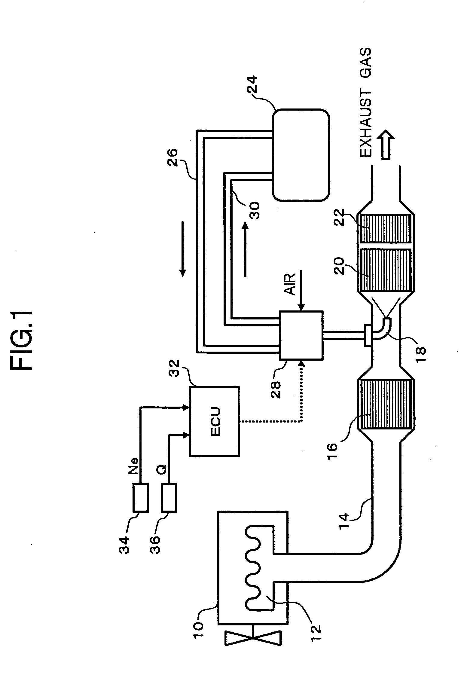
[0026]FIG. 1 shows an embodiment of a heater-attached piping according to the present invention applied to an exhaust gas purification device. In the exhaust gas purification device, urea aqueous solution is used as a reducing agent precursor, and nitrogen oxide (NOx) in engine exhaust is purified by catalytic reduction reaction.

[0027]An exhaust pipe 14 is connected to an exhaust manifold 12 of an engine 10. The following members are disposed in the exhaust pipe 14 along a flowing direction of exhaust gas, i.e., an oxidation catalytic converter 16 for oxidizing nitric oxide (NO) into nitrogen dioxide (NO2), an injection nozzle 18 for injecting and supplying a necessary amount of urea aqueous solution suitable for an operation state of an engine, a NOx reduction catalytic converter 20 for reducing and purifying NOx by ammonia obtained by hydrolyzing the urea aqueous solution, and...


PUM


Abstract

A heater-attached piping having, a cord-like heater disposed along substantially entire length of a nylon tube forming a pipe for transferring a fluid, and at least a heat-retaining layer disposed around the nylon tube and the cord-like heater. The cord-like heater located at the end of the nylon tube may be, for example, folded back and formed in a duplex arrangement. With this arrangement, heat generating at the end of the heater-attached piping increases and is duplicated to result in suppression of power consumption of the cord-like heater to a possible lowest limit, and the heat-retaining ability and defrosting ability in the end of the heater-attached piping can be enhanced.

Description

BACKGROUND OF THE INVENTION[0001]1. Field of the Invention[0002]The present invention relates to a piping with a heater attached thereto (hereinunder, wholly refer to as “heater-attached piping” throughout the specification and the appended claims) through which various fluid is transferred, and more particularly, to a technique for enhancing heat-retaining ability and defrosting ability in a piping end.[0003]2. Description of the Related Art[0004]There are a variety of home and industrial equipment and devices having piping connected thereto for allowing a fluid or liquid substance to flow therethrough. If there occurs condensation or freeze in an interior of the piping in, for example, water supply equipment, a gas analyzer or the like used in cold climates, such condensation or freeze will cause inconvenience and trouble with the equipment and apparatuses. Thus, a heater-attached piping is employed as shown in Japanese Unexamined PatentApplication Nos. 2003-27535 and 2002-246157....

Claims


Application Information

Patent Timeline
IPC IPC(8): H05B3/58
CPCH05B3/58
Inventor TANAKA, YASUHIROIZUMI, ATSUSHITSUDA, AKINOBU
Owner NISSAN DIESEL MOTOR CO
Learn More