Low-cost compact bar code sensor

a bar code sensor, compact technology, applied in the field of sensors, can solve the problems of high manufacturing cost, short working distance, inefficient and unreliable operation of bar code sensor systems, limit the application of bar code sensors in many fields, etc., to achieve better manufacturing accuracy, large working distance, and align more simply and more accurately

Active Publication Date: 2008-02-28
HONEYWELL INT INC
View PDF19 Cites 8 Cited by
  • Summary
  • Abstract
  • Description
  • Claims
  • Application Information

AI Technical Summary

Benefits of technology

[0011]Advantageously, by utilizing diffracting optical elements as the optical lenses for the emitter and detector, the optical lenses can be made more compact and can be aligned more simply and more accurately with the emitter and detector than optical lenses of prior art bar sensors. Furthermore, the diffraction optical elements can be mounted in the first level packaging without the need for second level packaging by disposing the diffraction optical elements on the respective emitter and detector.
[0012]The diffraction optical elements can be integrated into the wafer level using lithography enabling much better manufacturing accuracy and alignment accuracy. Thus, potential larger working distance and finer focus point can be reached and resolution of the sensor can be improved. Manufacturing the diffraction optical elements into the wafer level prior to sawing of the wafer, enables compact light source and photodetectors with well-aligned lens to be provided cheaply compared with prior art bar code sensors which employ light source and photodetectors with external aligned lens.

Problems solved by technology

The aforementioned known barcode systems are generally of large dimensions owing to the large space requirements of bulky lenses or other optics necessary for concentrating sufficient illumination both on the bar code to be scanned and the detector after reflection from the bar code target area.
The optics of such systems are complicated to align and assemble and suffer from optical inefficiencies which result in short working distances and higher than necessary power consumption requirements to compensate for these optical inefficiencies.
High manufacturing costs and inefficient and unreliable operation of these bar code sensor systems limit their applications in many fields.

Method used


Image

  • Low-cost compact bar code sensor
  • Low-cost compact bar code sensor
  • Low-cost compact bar code sensor

Examples


Embodiment Construction

[0036]The particular values and configurations discussed in these non-limiting examples can be varied and are cited merely to illustrate at least one embodiment of the present invention and are not intended to limit the scope of the invention.

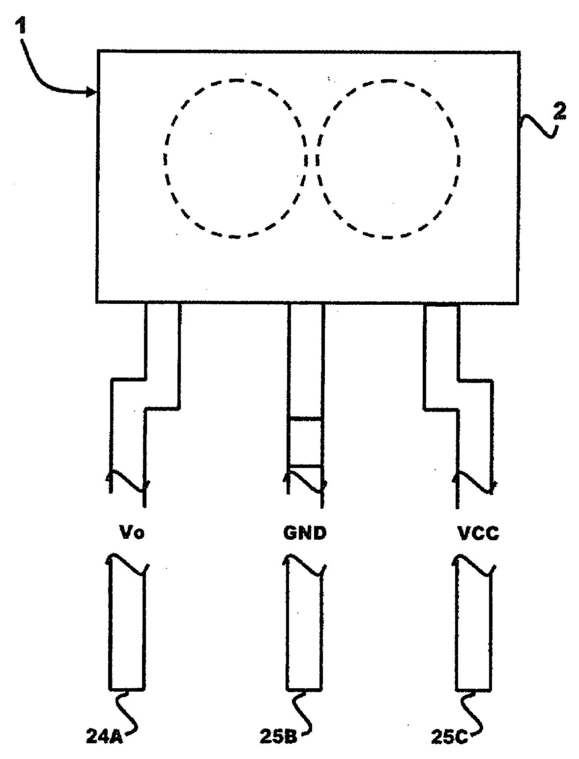
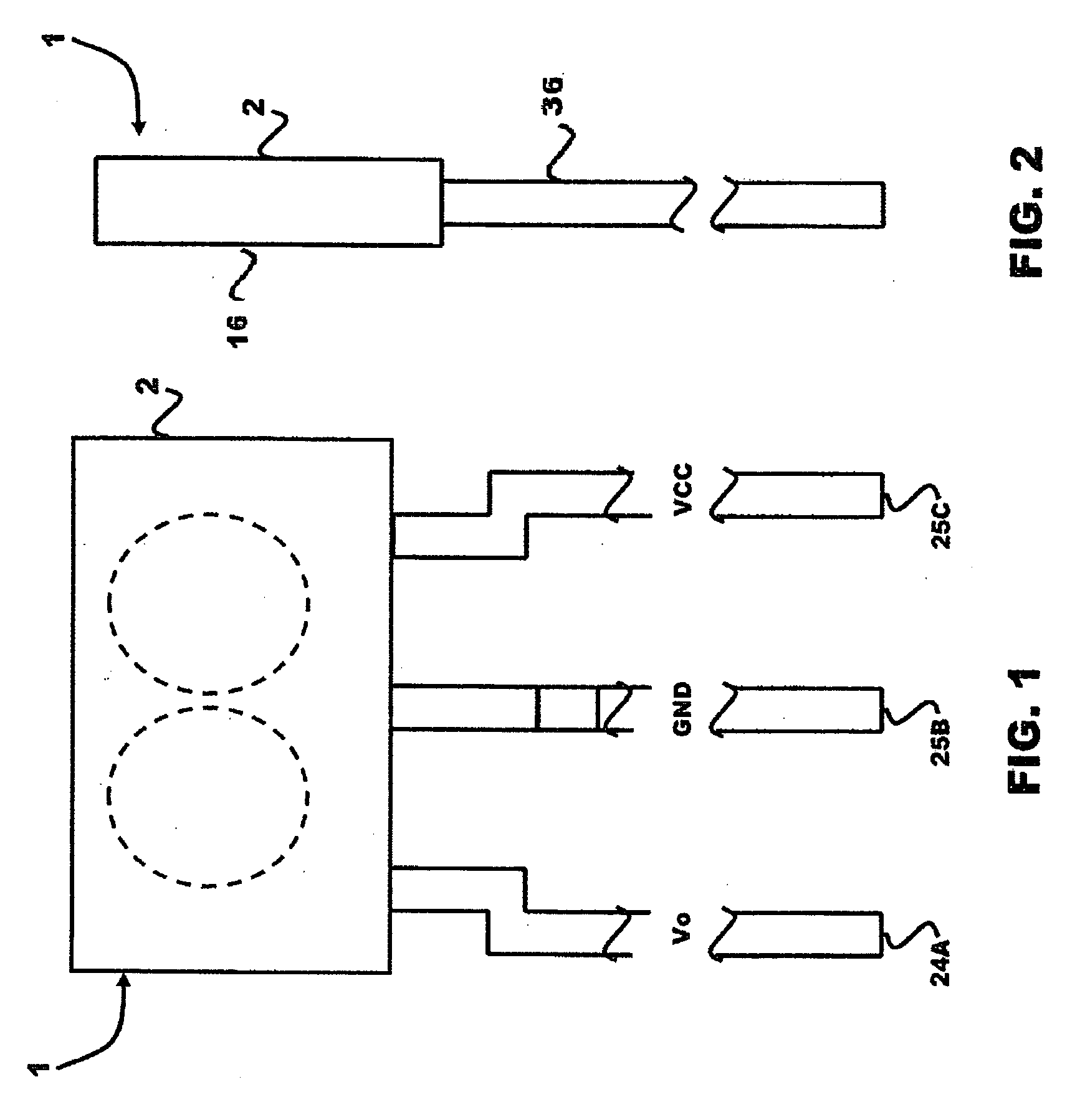
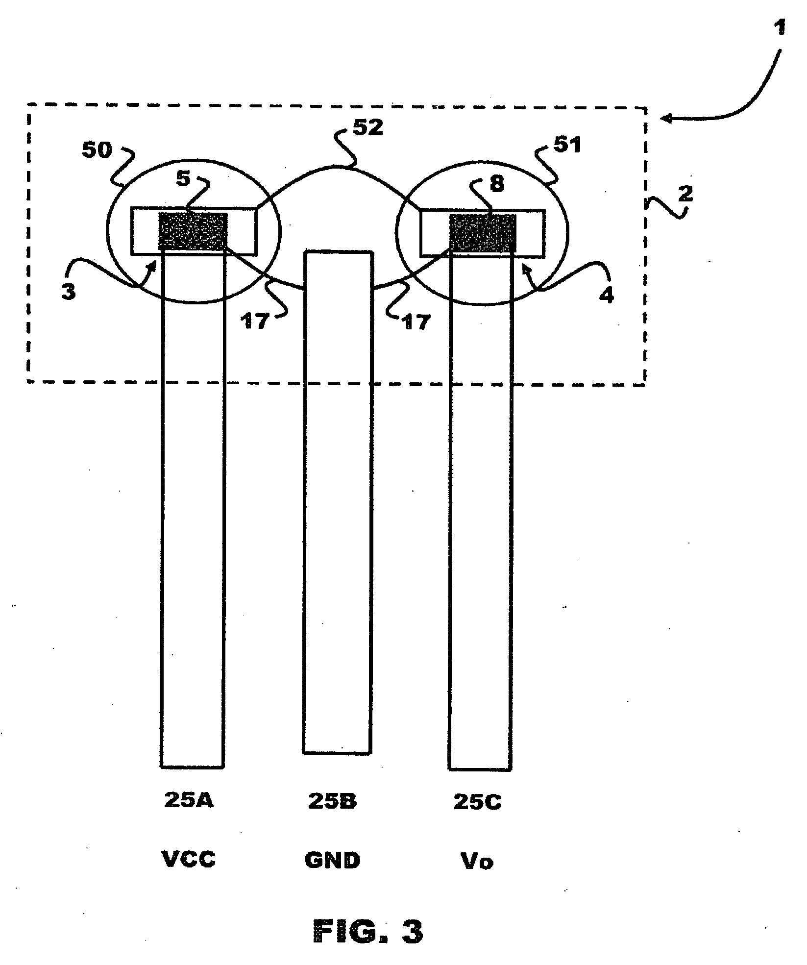
[0037]Referring to FIGS. 1 & 2 of the accompanying drawings, which illustrate side views of a bar code sensor according to one embodiment, and additionally FIG. 3, which illustrates the same side view as FIG. 1 but showing the components inside the housing, the bar code sensor 1 has a housing 2 defining apertures 50, 51 and a cavity in which are disposed an optical emitter circuit 3 and an optical detector circuit 4 thereby forming a sensor package. A lead frame 5 is integrated in the housing 2 for electrically connecting the optical emitter and detector circuits 3, 4 to an external printed circuit board or other external circuitry.

[0038]As best shown in FIG. 4, which illustrates a schematic diagram of the optical structure of the bar code sens...


PUM


Abstract

A barcode sensor package has an optical emitter circuit and an optical detector circuit which are formed as one or more integrated optical circuits disposed in a housing which has a reading surface and one or more apertures located between the optical emitter and detector circuits. The optical emitter circuit has an emitter die, such as a vertical cavity surface emitting laser (VCSEL), for emitting a light beam and a diffraction optical element disposed on the emitter die for focusing the light beam to a bar code. The optical detector circuit has a photodetector die, such as a phototransistor, for detecting reflective light and another diffraction optical element disposed on the photodetector die for guiding light reflected from the bar code to the detector. The diffraction optical elements are fabricated by patterning optical layers, deposited on respective emitter and detector dies, using photolithograph or a direct write process.

Description

TECHNICAL FIELD[0001]Embodiments are generally related to sensors and, in particular, to bar code sensors and methods of forming such sensors. Embodiments are additionally related to packaging bar code sensors. Also, embodiments are related to MEMS bar code sensors.BACKGROUND OF THE INVENTION[0002]Known barcode sensor systems generally use lasers in conjunction with conventional lenses or other optics for focusing or concentrating sufficient laser radiation on the bar code to be scanned. The systems additionally include detectors also in conjunction with conventional optics for receiving light reflected from a target area of the bar code and providing an output signal representing the bar code. Other barcode sensor systems utilize light emitting diodes (LEDs) as the light sources instead of lasers.[0003]A known bar code sensor of the prior art, for example the bar code sensor 300 shown in FIGS. 9A & 9B of the accompanying drawings, includes a light source and photodiode dies molded ...

Claims


Application Information

Patent Timeline
Patent Type & Authority Applications(United States)
IPC IPC(8): G06K7/10
CPCG06K7/10702
Inventor ZHANG, WENWEI
Owner HONEYWELL INT INC
Why Eureka
Try Eureka