Circuit and method for controlling quality of random numbers
- Summary
- Abstract
- Description
- Claims
- Application Information
AI Technical Summary
Benefits of technology
Problems solved by technology
Method used
Image
Examples
first embodiment
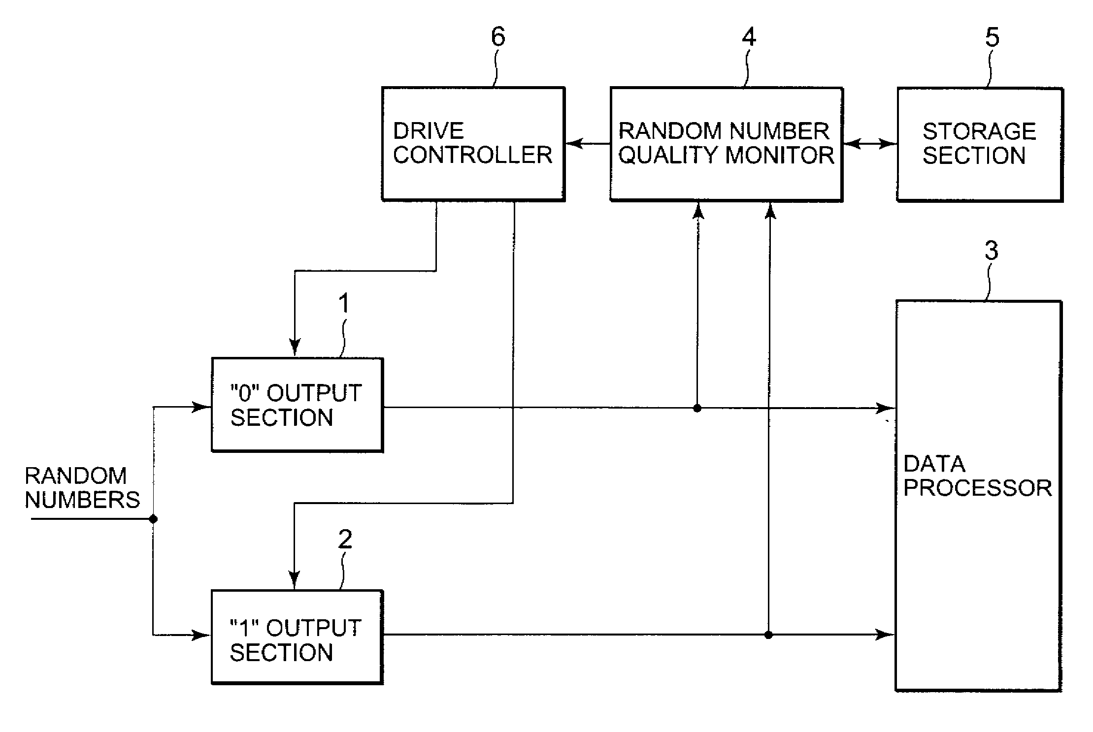
[0077]FIG. 7A is a block diagram showing a schematic configuration of a quantum key distribution system to which a random number quality control circuit according to a first embodiment of the present invention is applied. FIG. 7B is a table showing the operations of an optical circuit in the first embodiment. In the present embodiment, the detection efficiency η of a photon receiver, which is a reception efficiency of a receiver, is adjusted with DC bias so that the mark ratio of a sifted key is maintained at 50%.
[0078] Referring to FIG. 7A, in the quantum key distribution system according to the first embodiment, Alice (sender) 11 and Bob (receiver) 13 are connected through an optical fiber 12 and share a cryptographic key by superposing information on the phase of a photon to be transmitted. It is assumed that a photon enters any one of a photodetector 132 (hereinafter, referred to as photodetector 0) and a photodetector 133 (hereinafter, referred to as photodetector 1) depending...
second embodiment
[0091]FIG. 10 is a block diagram showing a schematic configuration of a quantum key distribution system to which a random number quality control circuit according to a second embodiment of the present invention is applied. In the second embodiment, DC biases to be applied to photodetectors 0 and 1 in Bob are changed based on the mark ratio Rm of a sifted key obtained in Alice. On Alice's side, as will be described later, a random number source that generates physical random numbers is provided. Since a sifted key can be extracted based on these physical random numbers, DC bias control based on the mark ratio of the sifted key can be further enhanced in precision. Note that the blocks having the same functions as the counterparts in FIG. 7A are denoted by the same reference numerals as in FIG. 7A, and detailed description thereof will be omitted.
[0092] Referring to FIG. 10, in the quantum key distribution system according to the present embodiment, Alice 21 and Bob 23 are connected ...
third embodiment
[0104]FIG. 12A is a block diagram showing a schematic configuration of a quantum key distribution system to which a random number quality control circuit according to a third embodiment of the present invention is applied. FIG. 12B is a table showing the operations of an optical circuit in the third embodiment. Note that the blocks having the same functions as the counterparts in FIG. 7A are denoted by the same reference numerals as in FIG. 7A, and detailed description thereof will be omitted.
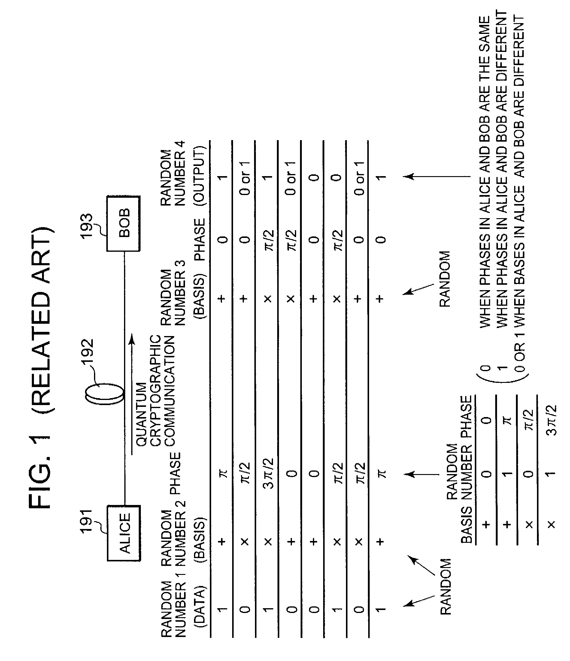
[0105] In the present embodiment, adjustment is performed in combination with the mark ratio improving method based on Bethune described with reference to FIG. 5. As described with FIG. 5, the probabilities of obtaining “0” and “1” in a sifted key are as follows; (probability of obtaining “0”)=P 1+P 3=S 1*Q 0+S 3*Q 1(probability of obtaining “1”)=P 2+P 4=S 2*Q 1+S 4*Q 4
As described already, in the system of the present embodiment, coding is performed such ...
PUM
 Abstract
Description
Claims
Application Information
 - R&D
- Intellectual Property
- Life Sciences
- Materials
- Tech Scout
- Unparalleled Data Quality
- Higher Quality Content
- 60% Fewer Hallucinations
Browse by: Latest US Patents, China's latest patents, Technical Efficacy Thesaurus, Application Domain, Technology Topic, Popular Technical Reports.
© 2025 PatSnap. All rights reserved.Legal|Privacy policy|Modern Slavery Act Transparency Statement|Sitemap|About US| Contact US: help@patsnap.com


