Power electronic package having two substrates with multiple semiconductor chips and electronic components

a technology of power electronic package and electronic components, which is applied in the direction of semiconductor devices, semiconductor/solid-state device details, electrical apparatus, etc., can solve the problem of reducing the heat resistance of the power electronic package, and achieve the effect of improving reliability and heat radiation performan

Active Publication Date: 2008-03-06
DENSO CORP +2
View PDF17 Cites 71 Cited by
  • Summary
  • Abstract
  • Description
  • Claims
  • Application Information

AI Technical Summary

Benefits of technology

[0009]In the above package, a uniform stress distribution in the package is...

Problems solved by technology

The direct double-side cooled configuration further r...

Method used


Image

  • Power electronic package having two substrates with multiple semiconductor chips and electronic components
  • Power electronic package having two substrates with multiple semiconductor chips and electronic components
  • Power electronic package having two substrates with multiple semiconductor chips and electronic components

Examples


first embodiment

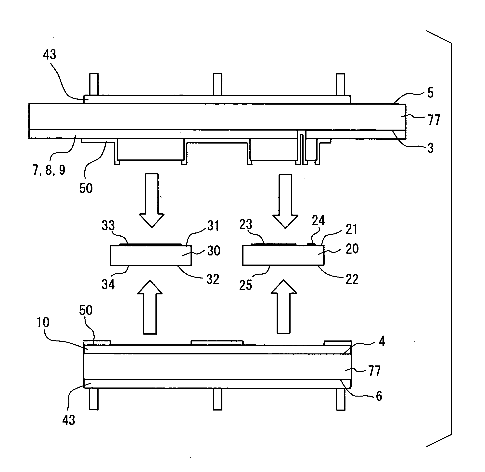
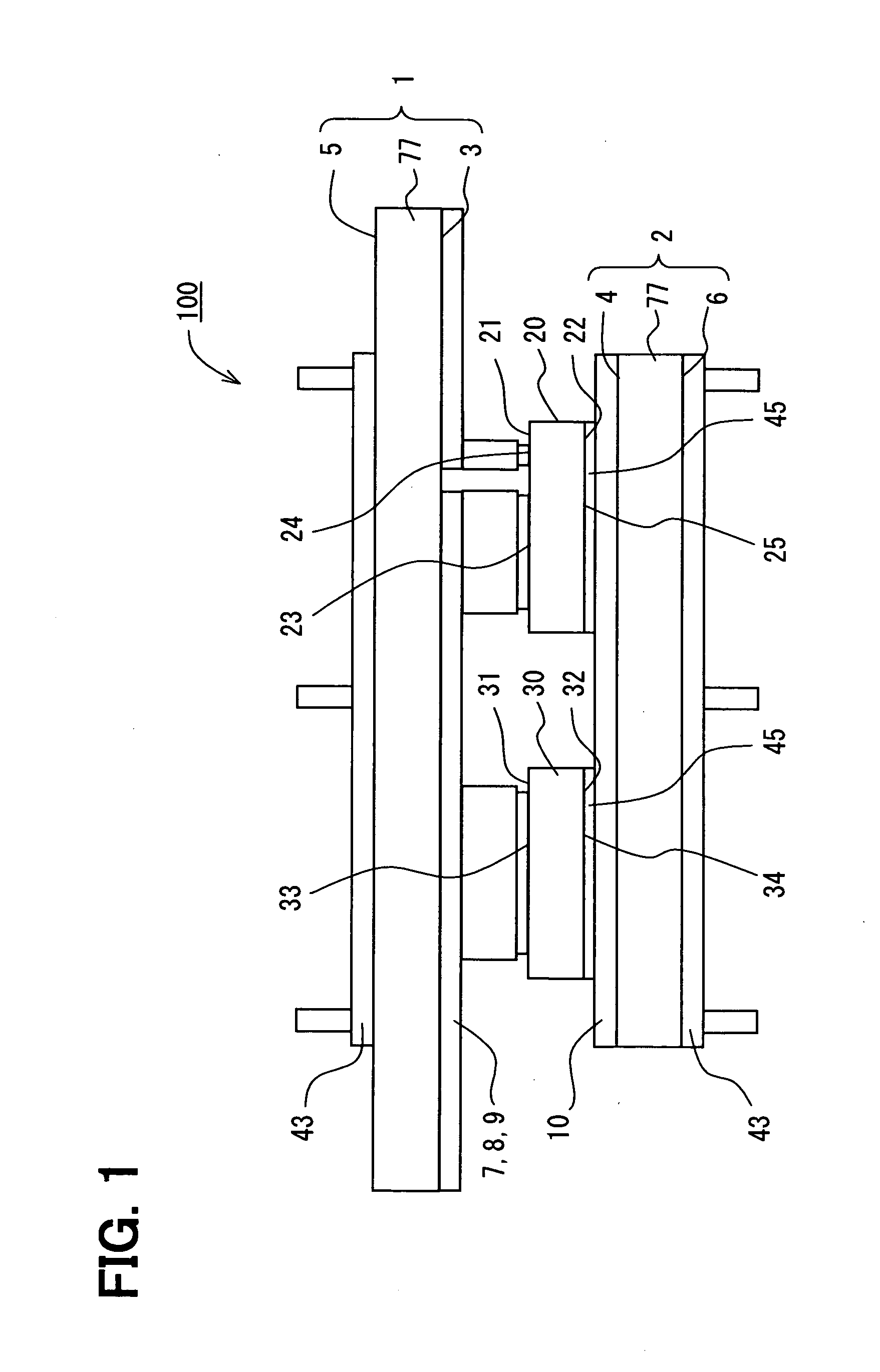
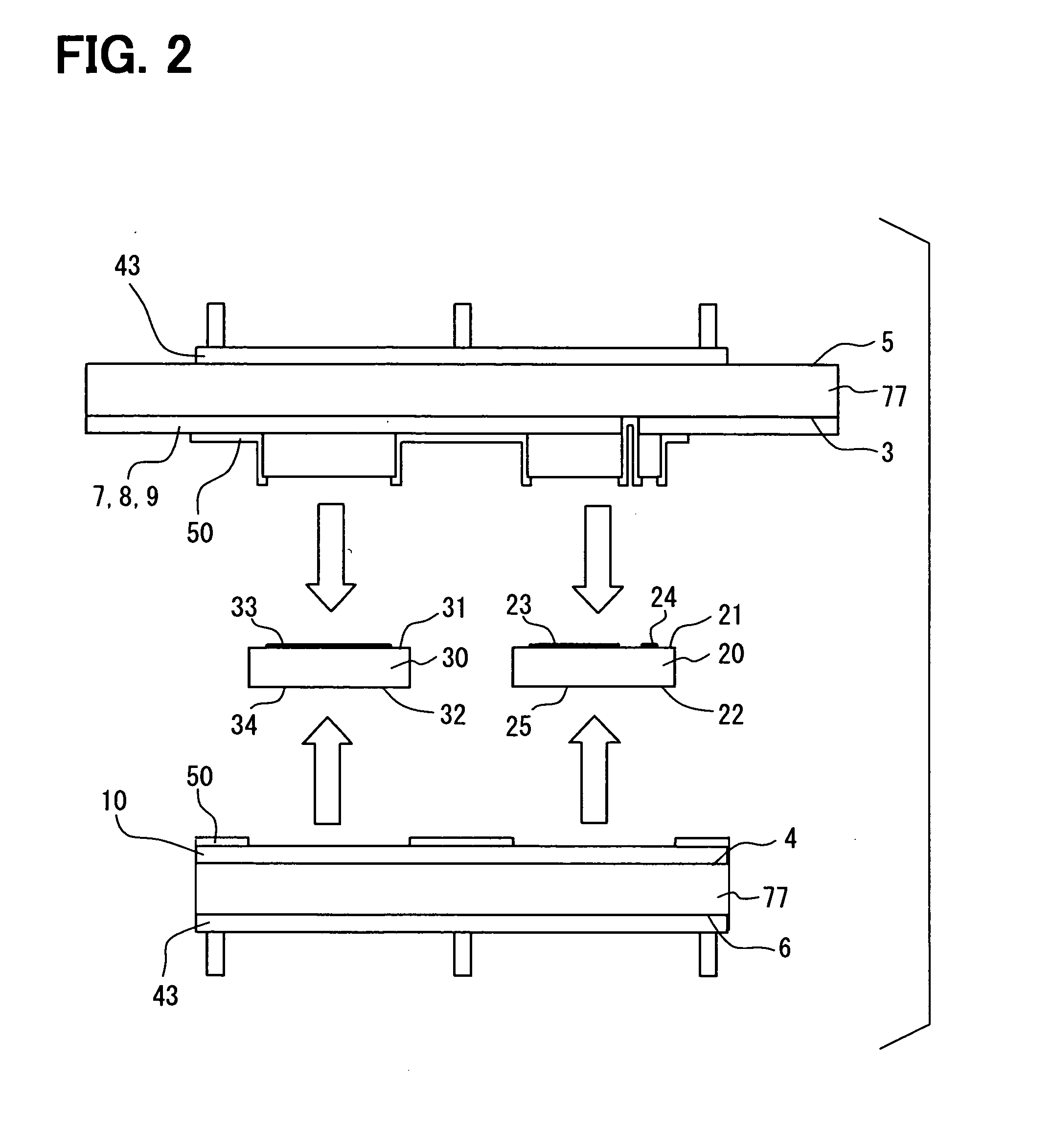
[0094]As shown in FIG. 31, each outer surface of the two high thermal conductive insulating non-planar substrates 1, 2 has not been etched for the improved integration with the heat exchanger 80. This example embodiment provide a freedom to use a integrated as well as a non integrated heat exchanger 80 for cooling the both side of the sandwich structure. The flat outer surface of the two high thermal conductive insulating non-planar substrates 1, 2 is suitable for using closed type micro-channel heat exchanger 80 unit using a thermal component in between to improve the heat radiation performance. However, this leads to a larger thermal resistance of the power electronic package 100. However, this configuration relaxes the total stress on the sandwich structure due to lack of direct bonding of the heat exchanger 80 unit. This structure can also be mounted on the air-cooled heat exchanger 80 units. The rest of the construction is the same as that of the With this kind of construction...

fourth embodiment

[0100]As shown in FIG. 37, each outer surface of the two high thermal conductive insulating non-planar substrates 1, 2 has not been etched for the improved integration with the heat exchanger 80. This embodiment provide a freedom to use a integrated as well as a non integrated heat exchanger 80 for cooling the both side of the sandwich structure. Each flat outer surface of the two high thermal conductive insulating non-planar substrates 1, 2 is suitable for using closed type micro-channel heat exchanger 41 unit using a thermal component in between to improve the heat radiation performance. However, this leads to a larger thermal resistance of the power electronic package 100. However, this configuration relaxes the total stress on the sandwich structure due to lack of direct bonding of the heat exchanger 80 unit. This structure can also be mounted on the air-cooled heat exchanger 80 units. The rest of the construction is the same as that of the With this kind of construction also, ...


PUM


Abstract

A power electronic package includes: first and second high thermal conductivity insulating non-planar substrates; and multiple semiconductor chips and electronic components between the substrates. Each substrate includes multiple electrical insulator layers and patterned electrical conductor layers connecting to the electronic components, and further includes multiple raised regions or posts, which are bonded together so that the substrates are mechanically and electrically connected. The number, arrangement, and shape of the raised regions or posts are adjusted to have mechanical separation between the substrates. The electrical conductor layers are separated and isolated one another so that multiple electric circuits are provided on at least one of the substrates.

Description

FIELD OF THE INVENTION[0001]The present invention relates generally to a power electronic package having two substrates with multiple semiconductor chips and electronic components.BACKGROUND OF THE INVENTION[0002]High-performance power electronic devices continue to make great strides in voltage, current and power levels. But the higher performance comes with higher power dissipation levels that place a strain on electrical interconnections, on cooling and on mechanical integrity. Conventional approaches to packaging power electronic devices use discrete packaged devices mounted onto a board or substrate or a hybrid module, in which bare chips are mounted onto the substrate and connected to the substrate by wire bonds, and therefore, the conventional techniques have significant performance limitations. The discrete package can be plastic molded, metal sealed cans or sealed ceramic carriers, and the package contains one power chip wire bonded to a plastic package lead frame. The bare...

Claims


Application Information

Patent Timeline
IPC IPC(8): H01L23/48
CPCH01L23/49844H01L23/5385H01L2924/13062H01L2924/12032H01L2924/1305H01L2924/13091H01L2924/13055H01L24/31H01L24/83H01L25/072H01L25/18H01L2224/81894H01L2224/83801H01L2224/83894H01L2924/01079H01L2924/00H01L2224/33H01L23/3735
Inventor MALHAN, RAJESH KUMARJOHNSON, C. MARKBUTTAY, CYRILRASHID, JEREMYUDREA, FLORIN
Owner DENSO CORP
Why Eureka
Try Eureka