
Method for membrane filtration purification of suspended water

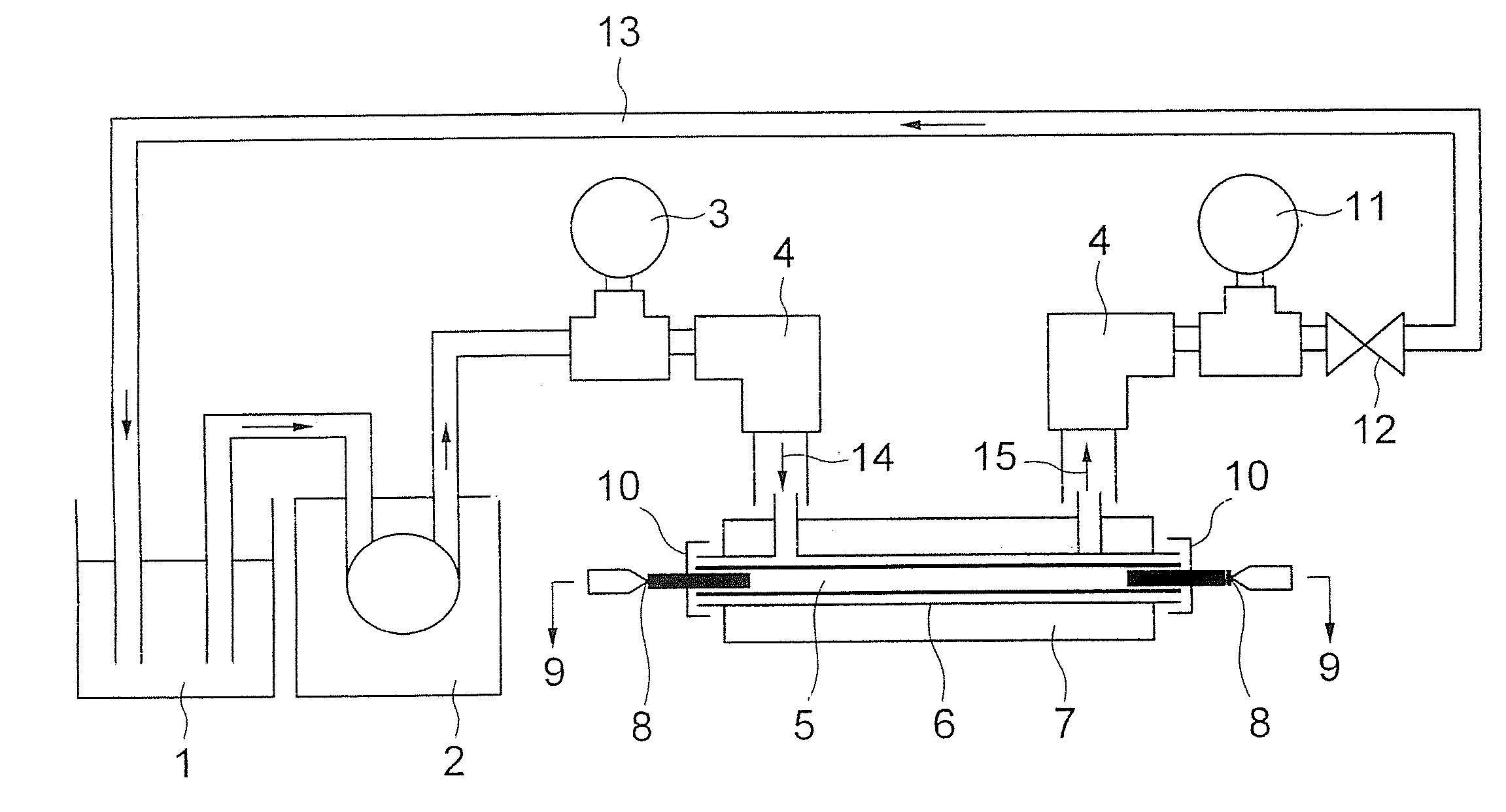
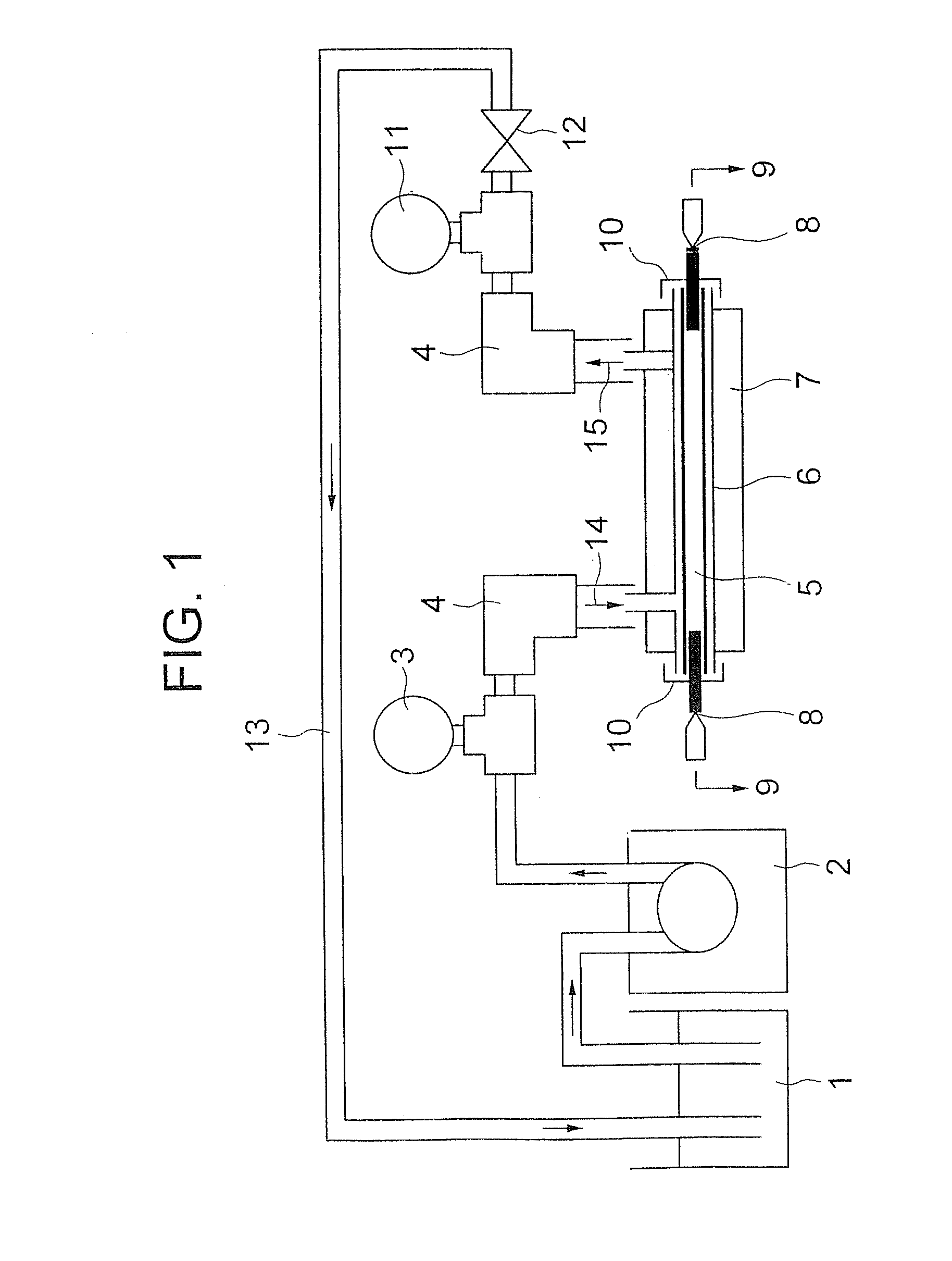
a technology of membrane filtration and suspended water, which is applied in the field of clarification methods, can solve the problems of deterioration of permeability of membrane filtration, wide spread of membrane filtration methods, and hinderance to a stable operation of membrane filtration, so as to achieve superior filtration stability and reduce the effect of deterioration of permeability

Inactive Publication Date: 2008-03-20
ASAHI KASEI CHEM CORP
View PDF4 Cites 0 Cited by
  • Summary
  • Abstract
  • Description
  • Claims
  • Application Information

AI Technical Summary

Benefits of technology

[0006] An object of the present invention is to provide a clarification method comprising a membrane filtration process for clarifying natural water, domestic wastewater and suspended water, which is treated water thereof, said process is lowered in deterioration of permeability due to fouling of membrane and in deterioration of permeability due to abrasion on membrane surface and is superior in filtration stability.
[0007] The present inventors, having made extensive efforts to solve the above described problems, found out that the use of a membrane with high open area ratio in an outer surface could reduce the deterioration of permeability due to fouling and the deterioration of permeability due to abrasion on a membrane surface and enhance filtration stability of the membrane, and thus accomplished the present invention.
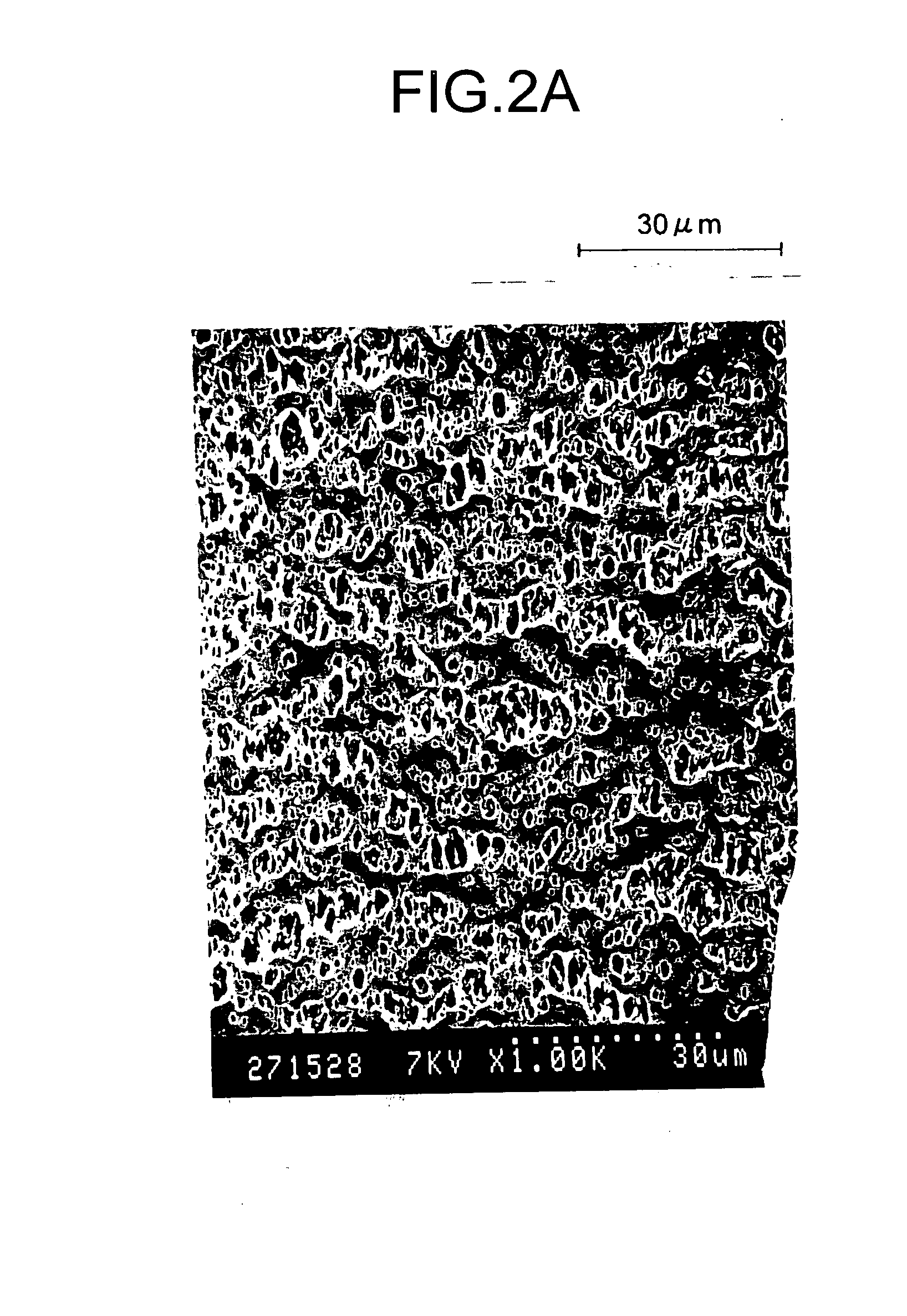
[0009] The deterioration of permeability due to fouling has been generally considered so far to be associated with levels of pure water flux, porosity and further pore diameters, which are fundamental properties of membrane. However, the present inventors have found out that, as described practically in Examples later, within a certain range of pore diameter, retention of permeability (degree of deterioration of permeability; the lower the retention of permeability is, the severer the deterioration is), in filtration of suspended water, has no relation to levels of pure water flux, porosities and pore diameter but is determined by the degree of open area ratio in an outer surface. That is, the present inventors have found that the larger the open area ratio in an outer surface is, the larger the retention of permeability is. This means that even the membranes having the same pure water flux, porosities and pore diameters, may have different retentions of permeability (degree of deterioration of permeability), if they have different open area ratios in their outer surfaces, and thus shows an importance of an open area ratio in an outer surface for suppression of deterioration of permeability due to fouling.
[0010] Abrasion on membrane surface has been considered to occur not during filtering operation but mainly during the process of removing suspended substances accumulated on the outer membrane surface in external pressure type filtration by air cleaning etc. However, the phenomenon itself has not been well known and thus there has been little development in technology addressing the deterioration of permeability due to abrasion on membrane surface. There has only been made mention that using a membrane having high breaking strength is effective (see JP-A-1999-138164). The present inventors have obtained knowledge that use of a membrane with high open area ratio in an outer surface is also advantageous against the deterioration of permeability due to abrasion on membrane surface. The present invention has been accomplished based on this knowledge as a core concept.

Problems solved by technology

However, wider spread of a membrane filtration method is hindered because a technology enabling a long-term stable operation of membrane filtration has not been established (see, Y. Watanabe, R. Bian, Membrane, 24(6), 310-318 (1999)).
The most common hinderance to a stable operation of membrane filtration is the deterioration of the permeability of a membrane.
In addition, a membrane surface may be abraded by suspended substances to cause the deterioration of permeability.

Method used


Image

  • Method for membrane filtration purification of suspended water
  • Method for membrane filtration purification of suspended water
  • Method for membrane filtration purification of suspended water

Examples


example 1

[0055] A mixture of 20 parts by weight of high density polyethylene (SH800 from Asahi Kasei Corp.) and 80 parts by weight of diisodecyl phthalate (DIDP) was heated and mixed to a molten state (at 230° C.) in a twin screw extruder (TEM-35B-10 / 1V from Toshiba Machine Co., Ltd.). Then the above molten mixture was extruded through a circular ring hole for extrusion of molten material, having an outer diameter of 1.58 mm and an inner diameter of 0.83 mm, which is present in an extrusion face of a spinneret for hollow fiber formation, mounted at the extrusion exit in a head (230° C.) of the extruder tip. DIDP was discharged as a hollow part forming fluid through a round hole for injection of hollow part forming fluid, having 0.6 mm of diameter, which is present inside the circular ring hole for extrusion of molten material, and injected into a hollow part of the hollow fiber-like extrudate.

[0056] Hollow fiber-like extrudate extruded through the spinneret into air and was introduced into ...

example 2

[0057] A mixture of 20 parts by weight of high density polyethylene (Hizex Million 030S from Mitsui Chemical Co., Ltd.) and 80 parts by weight of diisodecyl phthalate (DIDP) were heated and mixed to a molten state (at 230° C.), in a twin screw extruder (TEM-35B-10 / 1V from Toshiba Machine Co., Ltd.). Then said molten material was extruded through a circular ring hole for extrusion of molten material, having an outer diameter of 1.58 mm and an inner diameter of 0.83 mm, which is present in an extrusion face of a spinneret for hollow fiber formation, mounted at extrusion exit in a head (230° C.) of extruder tip. DIDP was discharged as a hollow part forming fluid through a round hole for injection of hollow part forming fluid, having a diameter of 0.6 mm, which is present inside the circular ring hole for extrusion of molten material, and injected into a hollow part of hollow fiber-like extrudate.

[0058] Hollow fiber-like extrudate extruded through the spinneret into air was introduced ...

example 3

[0059] A mixture of 25.5 parts by weight of pulverized silica (R-972 from Nippon Aerosil Co., Ltd.) and 50.5 parts by weight of dibutyl phthalate (DBP) were mixed in a Henschel mixer, then 24.0 parts by weight of high density polyethylene (SH800 from Asahi Kasei Corp.) were further added thereto and mixed again in the Henschel mixer. The mixture was pelletized using a twin screw extruder. Pellets thus obtained were melted and mixed in a twin screw extruder (at 220° C.). The said molten material was extruded through a circular ring hole for extrusion of molten material, having an outer diameter of 1.58 mm and an inner diameter of 0.83 mm, which is present in an extrusion face of a spinneret for hollow fiber formation, mounted at extrusion exit in a head (220° C.) of extruder tip. Nitrogen gas was discharged as a hollow part forming fluid through a round hole for injection of a hollow part forming fluid, having a diameter of 0.6 mm, which is present inside the circular ring hole for e...


PUM

PropertyMeasurementUnit
pore diameteraaaaaaaaaa

Abstract

A method for membrane filtration purification of suspended water, comprising filtering the suspended water under an external pressure through a porous hollow fiber membrane comprising a polyolefin, a copolymer of olefin and halogenated olefin, halogenated polyolefin or a mixture thereof and having an open area ratio in an outer surface of not less than 20% and a pore diameter in a minimum pore diameter layer of not smaller than 0.03 μm and not larger than 1 μm.

Description

[0001] This application is a Divisional of co-pending application Ser. No. 10 / 181,355, filed on Jul. 17, 2002, the entire contents of which are hereby incorporated by reference and for which priority is claimed under 35 U.S.C. § 120.TECHNICAL FIELD [0002] The present invention relates to a clarification method to obtain clear water usable as drinking water, industrial water or the like from natural water such as river water, lake and marsh water and underground water as well as suspended water obtained by treating natural water, and to provide regenerated water for miscellaneous uses or the like, or clean water dischargeable into the environment from domestic wastewater such as sewage water and from suspended water obtained by treating domestic wastewater. BACKGROUND ART [0003] A procedure of solid-liquid separation (clarification process) to remove suspended substances is indispensable for clear water treatment to obtain drinking water or to obtain industrial water from natural wat...

Claims


Application Information

Patent Timeline
Patent Type & Authority Applications(United States)
IPC IPC(8): B01D61/14C02F1/00B01D67/00B01D69/02B01D69/08B01D71/26B01D71/34C02F1/44
CPCB01D61/14B01D67/003B01D69/02B01D69/08B01D67/0027B01D71/34B01D2323/12C02F1/444B01D71/26B01D71/261C02F1/44
Inventor KUBOTA, NOBORUIKEMOTO, TAKASHIHATAYAMA, HIROSHI
Owner ASAHI KASEI CHEM CORP
Learn More