Electrical Fuse Having Resistor Materials Of Different Thermal Stability

a technology of resistor materials and electrical fuse, which is applied in the direction of electrical apparatus, semiconductor devices, semiconductor/solid-state device details, etc., can solve the problems of less thermal stability, less thermal stability, and more likely to rupture the fuse in the second area, so as to reduce the voltage and reduce the risk of bursting

Inactive Publication Date: 2008-03-20
TOSHIBA AMERICA ELECTRONICS COMPONENTS
View PDF2 Cites 31 Cited by
  • Summary
  • Abstract
  • Description
  • Claims
  • Application Information

AI Technical Summary

Benefits of technology

[0013]The eFuses of the present invention provide for more reliable and predictable programming. In addition, the eFuses can be programmed with lower voltages due to the area of lower thermal stability.

Problems solved by technology

The eFuse is more likely to rupture in the second area upon application of a programming voltage due to the lower thermal stability of this material.
The thin layer of metal silicide in this area is less thermally stable than the thicker areas of metal silicide in the adjacent areas.
Therefore, the inner portion is more likely to rupture than the outer portion upon application of a programming voltage.

Method used


Image

  • Electrical Fuse Having Resistor Materials Of Different Thermal Stability
  • Electrical Fuse Having Resistor Materials Of Different Thermal Stability
  • Electrical Fuse Having Resistor Materials Of Different Thermal Stability

Examples


first embodiment

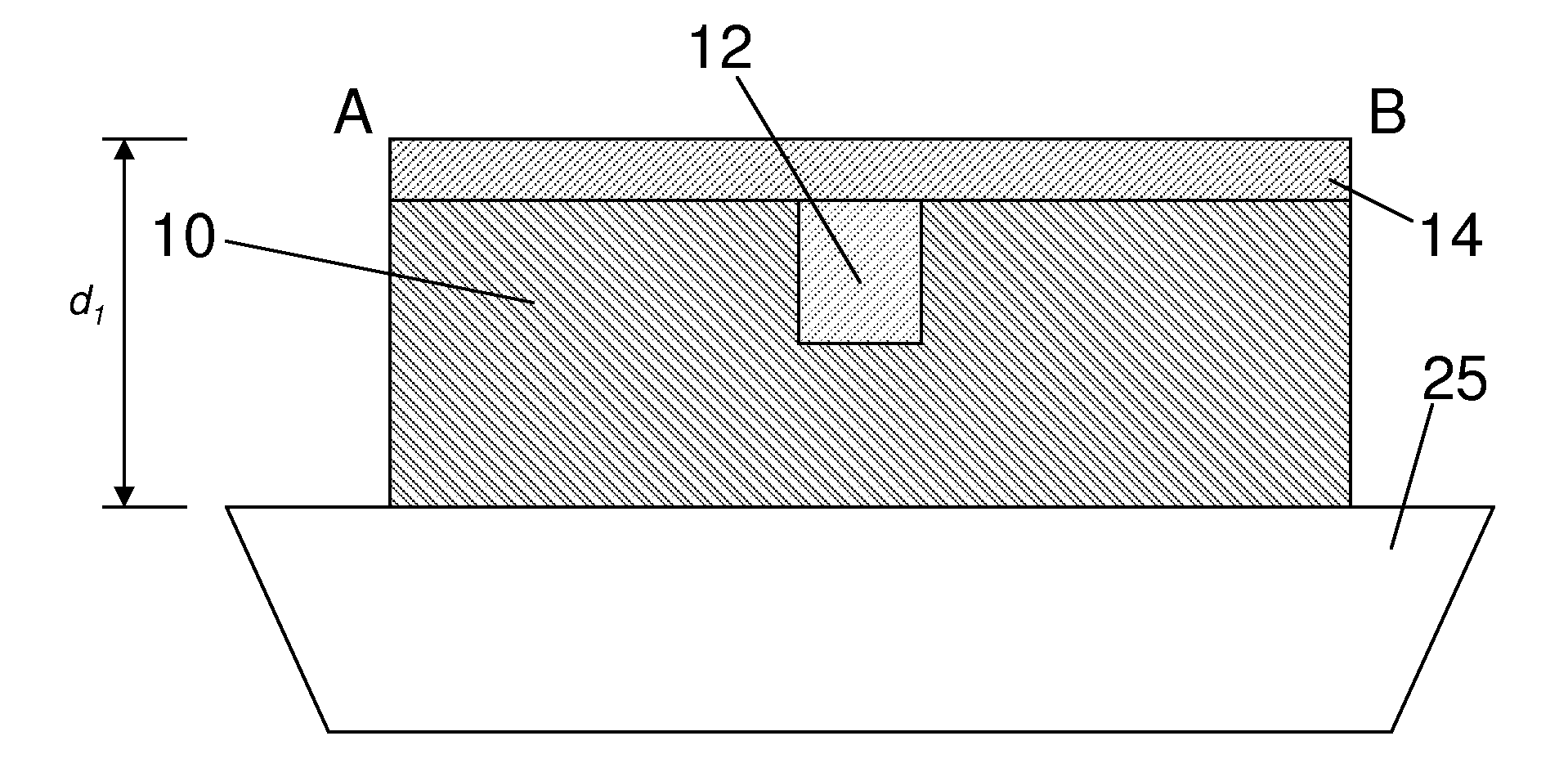
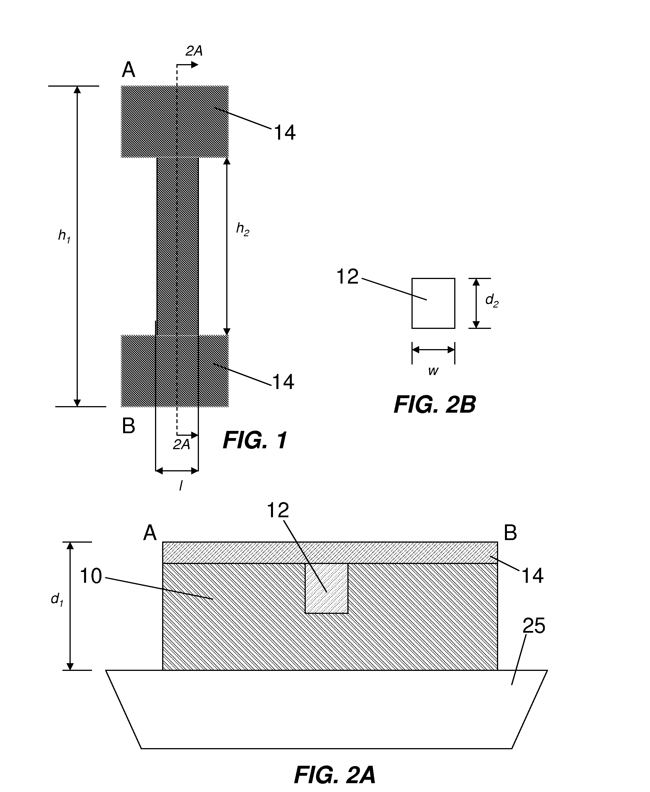
[0029]FIGS. 1 and 2A show top plan and cross-sectional views, respectively, of an eFuse according to the invention. The eFuse has a resistor formed on a shallow trench isolation (STI) substrate 25. The resistor has an outer portion 10 formed of polysilicon and an inner portion 12 formed of polysilicon germanium (poly-Si(1-x)Gex). The resistor also includes a metal silicide layer 14 over the outer 10 and inner 12 portions, defining a first area of nickel silicide on polysilicon and a second area of nickel silicide germanium (NiSi(1-y)Gey) on polysilicon germanium, respectively.

[0030]As an alternative to nickel silicide (NiSix), the metal silicide layer 14 can be selected from a number of types of other metal silicides, non-limiting examples of which include cobalt silicide (CoSix), titanium silicide (TiSix), palladium silicide (PdSix), platinum silicide (PtSix), ytterbium silicide (YbSix), and erbium silicide (ErSix), where x is 0.3 to 2.

[0031]As the term is used herein, an area is c...

second embodiment

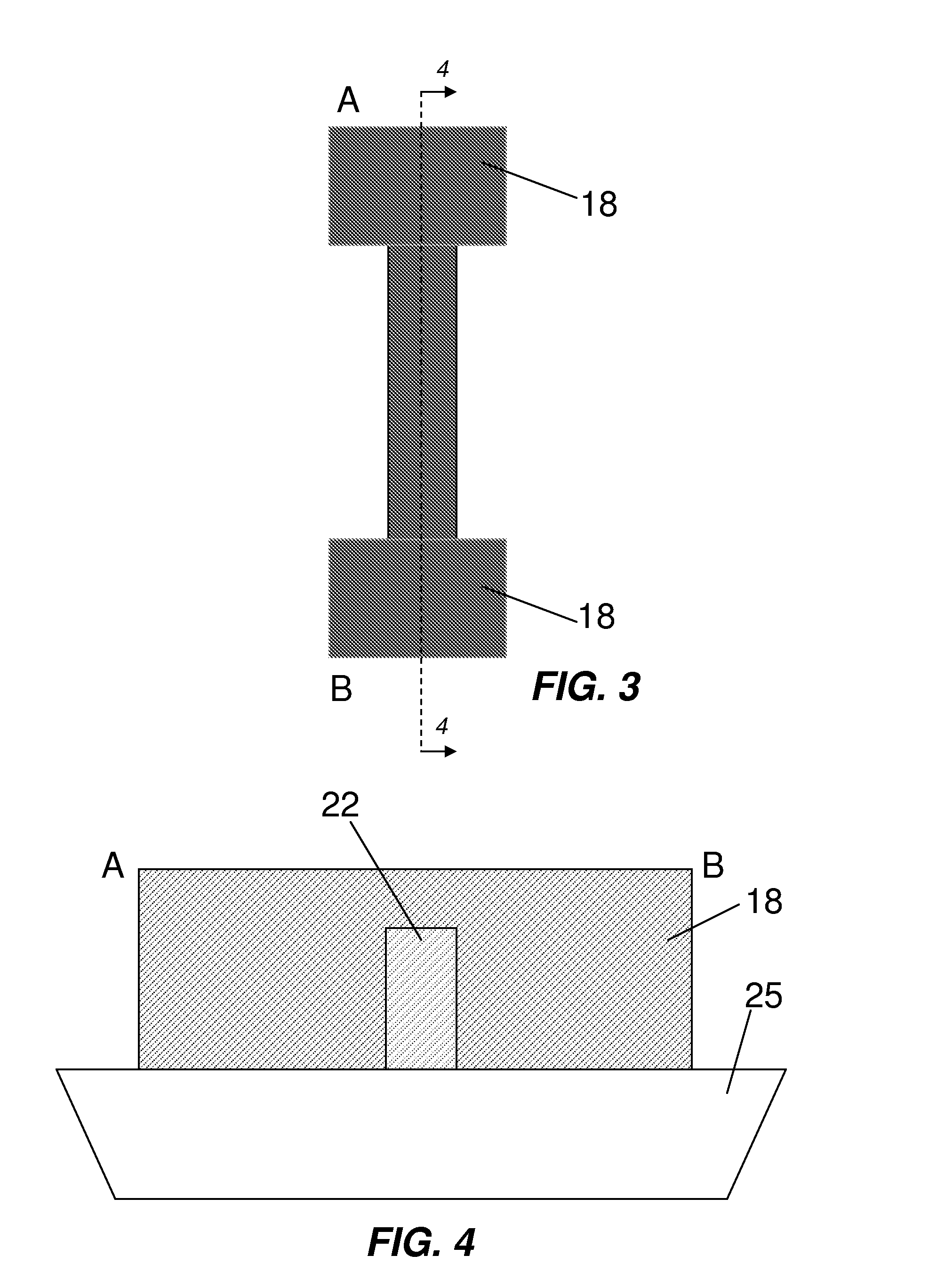
[0034]FIGS. 3 and 4 illustrate an eFuse in accordance with the invention utilizing a fully silicided (FUSI) gate. The eFuse has a resistor formed on an STI substrate 25. The resistor has an outer portion of metal silicide, such as nickel silicide 18 (NiSi), and an inner portion of polysilicon 22 formed on the substrate 25 and extending less than the full depth of the nickel silicide 18 layer. The first area is defined by the thicker portions of the nickel silicide 18, while the second area is defined by the thinner portion of the nickel silicide 18 overlying the polysilicon 22. The depth of the nickel silicide in the thin portion can range from about 10-100 nm, for example. This thin layer of NiSi is less thermally stable than the thicker NiSi portions in the adjacent areas because thin NiSi layers tend to agglomerate. Therefore, the second area is more likely to rupture than the first area upon application of a programming voltage.

[0035]The eFuse of the second embodiment can be man...

third embodiment

[0036]FIGS. 5 and 6 illustrate an eFuse in accordance with the invention. The eFuse has a two-metal resistor formed on an STI substrate 25. The resistor has an outer portion of a first metal, such as cobalt silicide 24 (CoSi2), and an inner portion of a second metal, such as nickel silicide 32. The first area is defined by the cobalt silicide 24, while the second area is defined by the nickel silicide 32. The thin nickel silicide 32 inner portion is less thermally stable than the thicker cobalt silicide 24 outer portion. Therefore, the nickel silicide 32 is more likely to rupture than the cobalt silicide 24 upon application of a programming voltage. Non-limiting examples of other combinations of first and second metals that can be used include NiSi2 and Ni3Si; W and NiSi; TiN and NiSi; and TaC and NiSi, respectively.

[0037]The eFuse of the third embodiment can be manufactured using a dual metal gate process with a replacement gate. This process is similar to FUSI except that this pro...


PUM


Abstract

An electrical fuse has a substrate and a resistor. The resistor has a first area and a second area embedded in the first area. The first area is formed of a first material and the second area is formed of a second material having a lower thermal stability than that of the first material. Because of the different thermal stabilities, the second area is more likely to rupture when a programming voltage is applied. The eFuse provides increased reliability and enables lower programming voltages to be used.

Description

FIELD OF THE INVENTION[0001]The present invention is directed to electrical fuses (eFuses) and, more particularly, to eFuses employing resistors manufactured with materials of different thermal stabilities.DESCRIPTION OF RELATED ART[0002]Electrical fuses (eFuses) have replaced laser fuses in many large scale integration (LSI) product chips due to several advantages, such as occupying less space on chips and increased flexibility in back-end integration schemes with a low-k dielectric. EFuses also are less prone to corrosion, crack, and splatter issues than are laser fuses.[0003]Most eFuses are designed to change the value of a resistor by rupturing it. In general, sensing voltage and programming voltage are sufficiently high (e.g., 3.3 V) to rupture the resistor. As process technology has progressed to smaller and smaller geometries, maximum operating voltages have been scaled downward, making it more difficult to get power to eFuses. Also, it is usually desirable to minimize the am...

Claims


Application Information

Patent Timeline
Patent Type & Authority Applications(United States)
IPC IPC(8): H01L29/00
CPCH01L23/5256H01L2924/0002H01L2924/00
Inventor MIYASHITA, KATSURA
Owner TOSHIBA AMERICA ELECTRONICS COMPONENTS
Why Eureka
Try Eureka