
Method for the manufacture of rod-shaped components

Inactive Publication Date: 2008-03-20
ENSINGER KUNSTTECH
View PDF5 Cites 4 Cited by
  • Summary
  • Abstract
  • Description
  • Claims
  • Application Information

AI Technical Summary

Benefits of technology

[0011]A great advantage of the method according to the invention is that the blank can first be obtained completely burr-free in an extrusion process, and that during the subsequent reshaping a cross-sectional change by means of an agglomeration of material is achieved free of cracks, without a thermal degradation or even an oxidation on the surface of the thermoplastic resin material having to be feared as a result. Furthermore, the mechanical values of the resin material are not impaired.
[0054]While an adequate centering of the blank in the tool is achieved with the three-jaw chuck, the four-jaw chuck has the advantage that it reacts in a geometrically neutral manner in the event of a thermal expansion.

Problems solved by technology

Such rod-shaped components with functional elements are usually manufactured in an injection molding process, however, a change in the rod length requires a very expensive new tool to be made.
Therefore, the changeover to production of a different length not only involves great expense, but also entails a considerable time requirement.
From a certain length of the rod-shaped component onwards, in particular, at lengths exceeding 1 m, the injection molding process reaches its limitations, and the material quality of the injection-molded part suffers.
Furthermore, all injection-molded parts have seams, which result from the tool being necessarily divided, and, in particular, when the rod-shaped components are used as joint pins, are disadvantageous because the desired perfectly cylindrical geometry is then not achieved.

Method used


Image

  • Method for the manufacture of rod-shaped components
  • Method for the manufacture of rod-shaped components
  • Method for the manufacture of rod-shaped components

Examples


Embodiment Construction

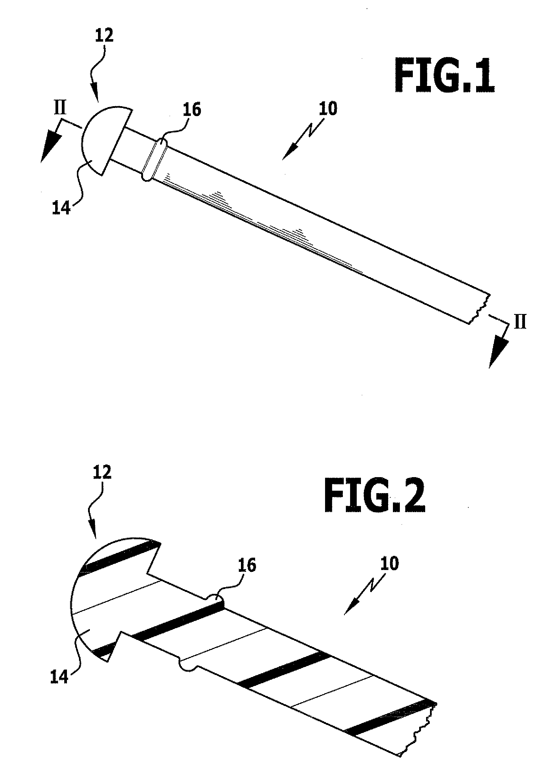
[0064]FIG. 1 shows a rod-shaped component according to the invention, generally designated by reference numeral 10, in the form of a joint pin with a substantially cylindrical shape. At one free end 12, the joint pin 10 has a spherical cap-shaped head 14, which was formed by reshaping a cylindrical blank in accordance with the method according to the invention. In this example, the diameter of the cylindrical blank is 3 mm.

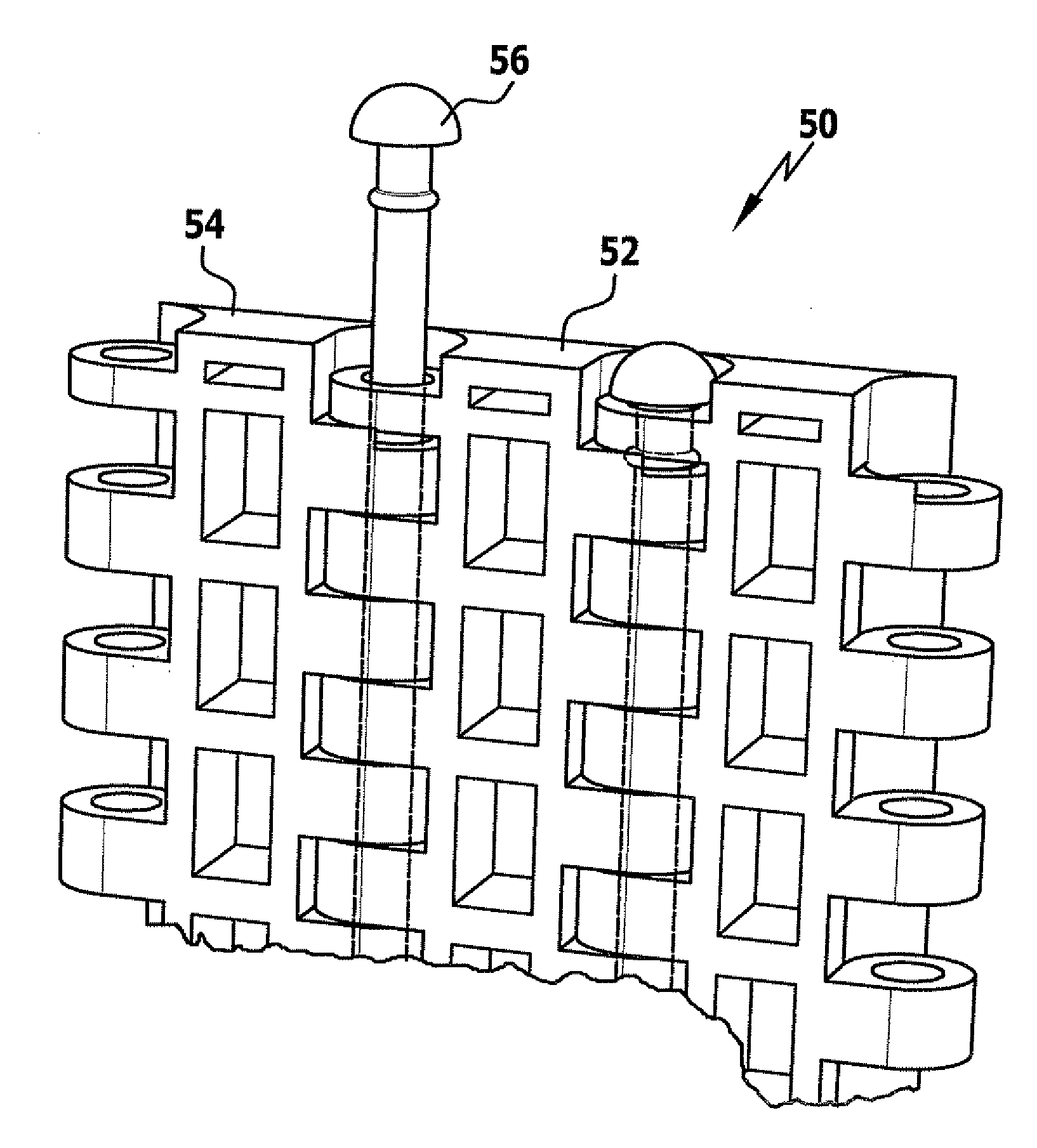
[0065]A ring collar 16 serving to lock the joint pin upon insertion into an associated joint connection (cf. FIG. 6) is formed at a spacing from the head 14 on the joint pin 10.

[0066]In the present case, the joint pin is made from a polyamide 6.6 material, which has a melting temperature of approximately 260° C.±5° C. The glass transition point in this material usually lies at approximately 70° C. to 50° C., depending on the moisture content of the material used.

[0067]The ideal working temperature here for the reshaping process lies above 110° C., in particular, i...


PUM

PropertyMeasurementUnit
Timeaaaaaaaaaa
Electric chargeaaaaaaaaaa

Abstract

To provide a method for the manufacture of rod-shaped components with one or more functional elements from a thermoplastic resin material, the length of the rod-shaped components being optionally variable, it is proposed that the method comprise the steps of producing in an extrusion process a blank having dimensions corresponding substantially to the rod-shaped component, and reshaping a portion of the blank to create a prescribed cross-sectional change by means of agglomeration of material in this portion, thereby to form the component with a functional element, the portion being heated prior to or during the reshaping to a reshaping temperature lying between the glass transition point and the melting point or softening point of the resin material.

Description

CROSS-REFERENCE TO RELATED APPLICATIONS[0001]The present disclosure claims the benefit of German application number 10 2006 045 736.6 of Sep. 18, 2006, which is incorporated herein by reference in its entirety and for all purposes.BACKGROUND OF THE INVENTION[0002]The invention relates to a method for the manufacture of rod-shaped components from a thermoplastic resin material.[0003]Rod-shaped components made from thermoplastic resin material are used in a large number of applications, in particular, as joint pin and the like, the rod-shaped components having functional elements, which necessitate an agglomeration of material, and comprise, for example, a head formed at their free end, and / or snap-in projections in the area between their ends.[0004]Such rod-shaped components with functional elements are usually manufactured in an injection molding process, however, a change in the rod length requires a very expensive new tool to be made. Therefore, the changeover to production of a d...

Claims


Application Information

Patent Timeline
IPC IPC(8): B29C57/00B28B11/00B29D99/00
CPCB29C43/021B29C43/16Y10T428/2976B29C2043/024B29L2001/002B29C43/361
Inventor EISENHARDT, DIETERHOFFMANN, STEPHANIE
Owner ENSINGER KUNSTTECH
Learn More