Onboard fuel cell system and method of discharging hydrogen-off gas

a fuel cell and fuel cell technology, applied in the field of onboard fuel cell systems and methods of discharging hydrogenoff gas, can solve the problems of hydrogen-off gas catching fire and not much attention, and achieve the effect of reducing the concentration of hydrogen smoothly

Inactive Publication Date: 2008-03-20
TOYOTA JIDOSHA KK
View PDF17 Cites 19 Cited by
  • Summary
  • Abstract
  • Description
  • Claims
  • Application Information

AI Technical Summary

Benefits of technology

[0010] It is thus an object of one aspect of the invention to provide an onboard fuel cell system and a method of discharging hydrogen-off gas which are capable of solving the aforementioned problem and discharging hydrogen-off gas to the atmosphere while reducing the concentration of hydrogen to a sufficiently low level.
[0013] Thus, the onboard fuel cell system according to one aspect of the invention or the method of discharging hydrogen gas according to another aspect of the invention is designed such that hydrogen-off gas that has been discharged from the fuel cell is mixed with oxygen-off gas that has also been discharged from the fuel cell. Because oxygen-off gas is nitrogen-rich gas, the aforementioned mixture of the gases makes it possible to dilute hydrogen-off gas and reduce the concentration of hydrogen contained in the mixed gases. Accordingly, it becomes possible to discharge the mixed gases to the atmosphere after the concentration of hydrogen has been reduced.
[0015] This construction ensures that gases will be discharged into the atmosphere from the opening at the end of the flow passage while being diffused in the radial direction of the opening. The exhaust gas (hydrogen-off gas) that has thus been discharged and diffused all over more often comes into contact with air surrounding the end of the flow passage, and is diluted correspondingly. Thus, the concentration of hydrogen can be reduced smoothly at the end of the flow passage.

Problems solved by technology

However, not much attention has been paid to hydrogen-off gas that has already been consumed to generate electric power in the fuel cell.
Therefore, if the concentration of hydrogen in gases discharged to the atmosphere is increased while something that could act as an ignition source is located close to an exhaust port through which the gases are discharged, there is a danger that hydrogen-off gas will catch fire.

Method used


Image

  • Onboard fuel cell system and method of discharging hydrogen-off gas
  • Onboard fuel cell system and method of discharging hydrogen-off gas
  • Onboard fuel cell system and method of discharging hydrogen-off gas

Examples


first embodiment

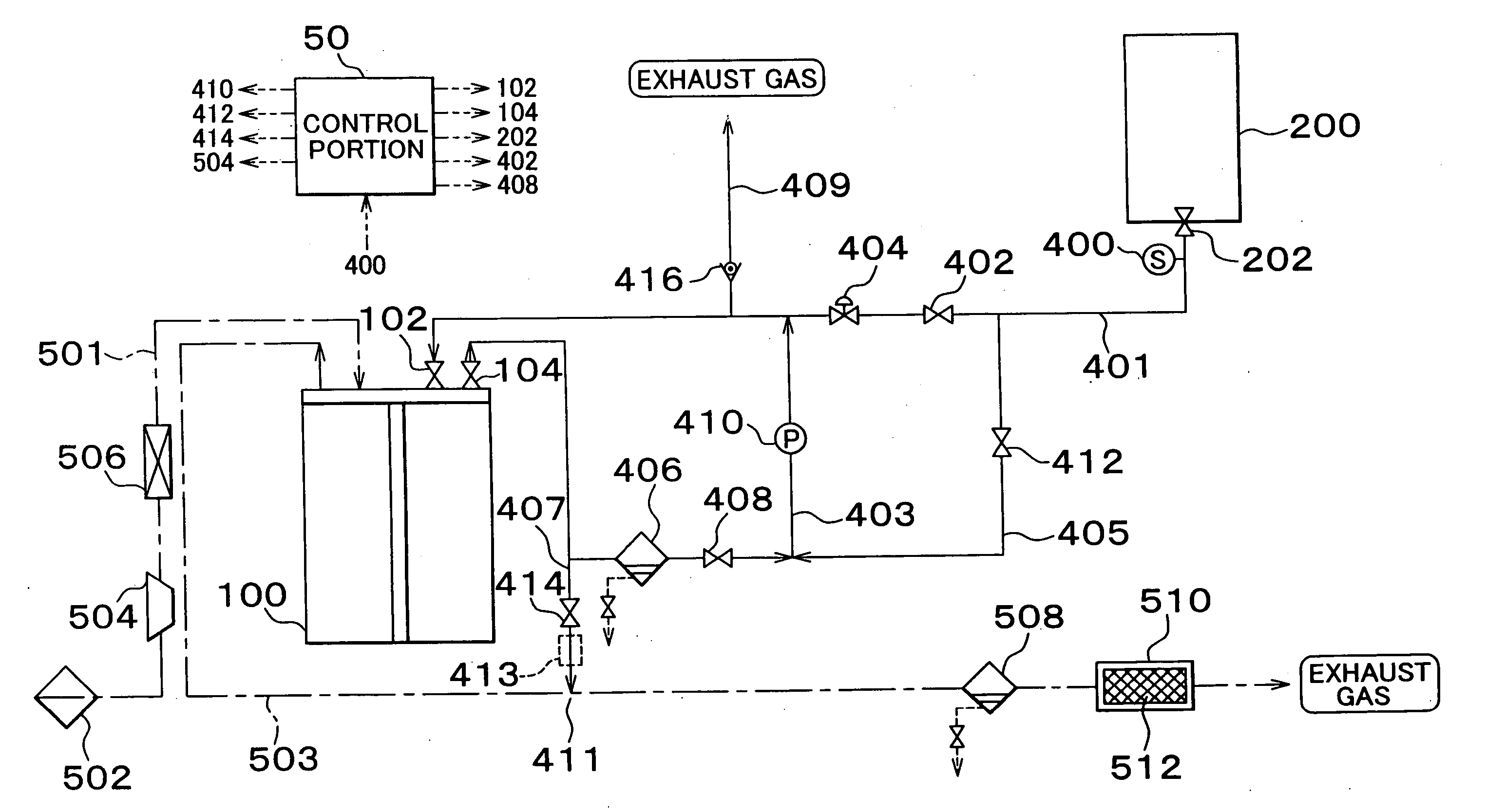
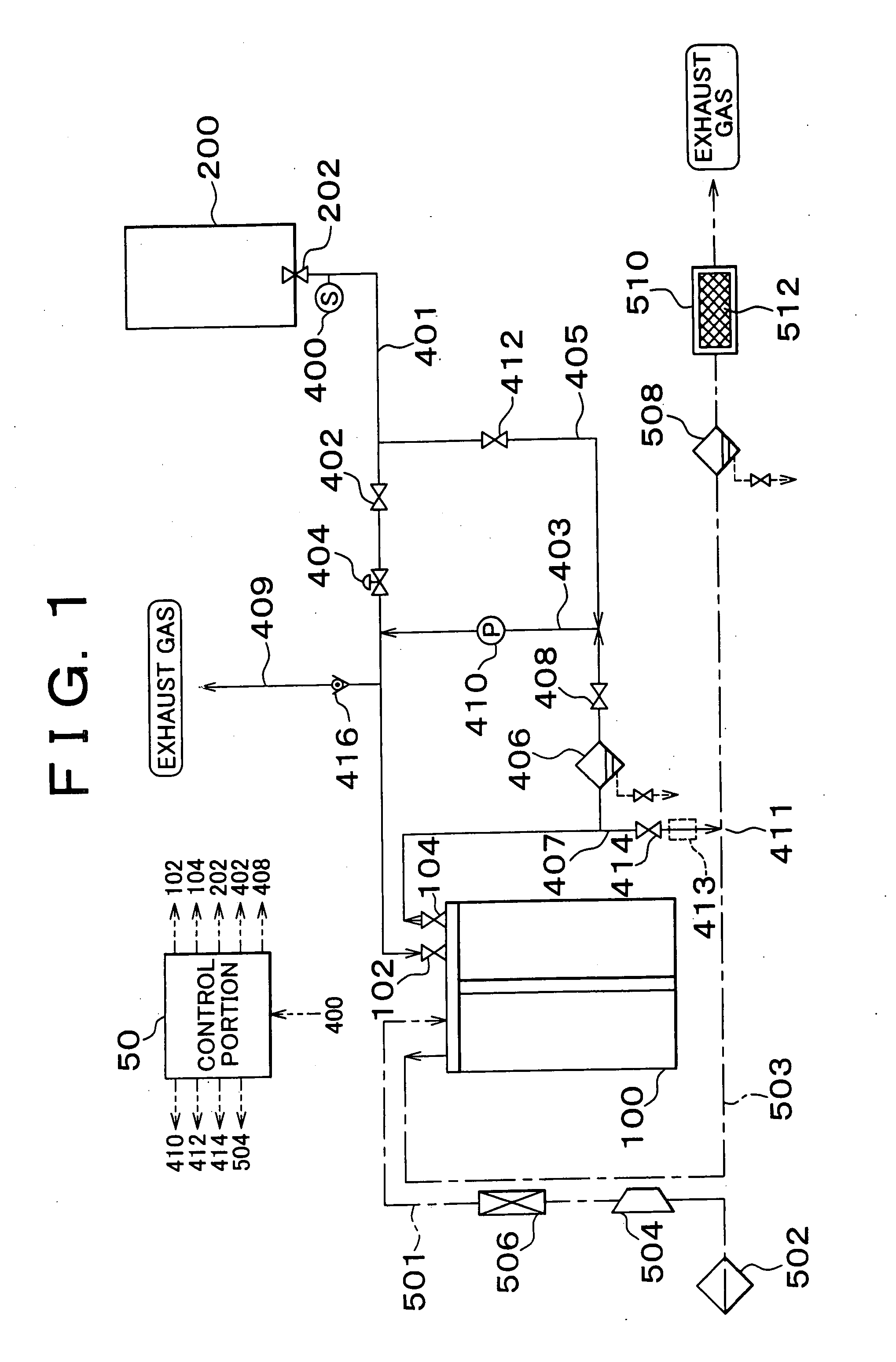
[0029]FIG. 1 is a block diagram of an onboard fuel cell system according to the invention. The fuel cell system of this embodiment is designed to be installed in a vehicle such as an automobile or the like, and is mainly composed of a fuel cell 100 and a hydrogen-occluding alloy tank 200. The fuel cell 100 is supplied with hydrogen gas and generates electric power. The hydrogen-occluding alloy tank 200 supplies the fuel cell 100 with hydrogen gas.

[0030] The fuel cell 100 is supplied with oxidative gas containing oxygen (e.g., air) as well as hydrogen gas containing hydrogen, causes electrochemical reactions in its anode (hydrogen pole) and cathode (oxygen pole) according to reaction formulae shown below, and generates electric power.

[0031] That is, if the anode and the cathode are supplied with hydrogen gas and oxidative gas respectively, the reactions according to the formulae (1) and (2) occur on the anode side and the cathode side respectively. As a whole, the reaction according...

third embodiment

[0096] In the fuel cell system of the third embodiment, as shown in FIG. 7, the hydrogen gas flow passage and the oxidative gas flow passage of the fuel cell system are partially different in construction from those of the aforementioned embodiments.

[0097] As in the case of the aforementioned embodiments, the hydrogen gas flow passage has the main flow passage 401 extending from the high-pressure hydrogen gas tank 300 to the fuel cell 100, the circulation flow passage 403 of the fuel cell 100, the exhaust flow passage 407 designed to discharge impurities, and the relief flow passage 409 designed to discharge hydrogen gas at the time of application of an abnormal pressure. In addition, the hydrogen gas flow passage of this embodiment has another relief flow passage 430, a leak check flow passage 427, and a supply flow passage 432. The relief flow passage 430 is designed to enhance the reliability in discharging hydrogen gas at the time of application of an abnormal pressure. The leak...

second embodiment

[0098] In addition to the shut valve 302 disposed at the discharge port of the high-pressure hydrogen gas tank 300, the main flow passage 401 has a discharge manual valve 304, the pressure-reducing valve 418, a heat exchanger 420, and the pressure-reducing valve 422. As in the case of the second embodiment, the circulation flow passage 403 is provided with the gas-liquid separator 406 and the like and causes hydrogen-off gas to circulate through the check valve 426 by means of the pump 410. A check valve 306 and a filling manual valve 308 are disposed in the supply flow passage 432 at the filling port of the high-pressure hydrogen gas tank 300. The exhaust flow passage 407 has the shut valve 414 and a hydrogen diluter 424. The relief flow passages 430, 409 have a relief valve 415 and the relief valve 416 respectively. The leak check flow passage 427 has a leak check port 428.

[0099] As in the aforementioned embodiments, the oxidative gas flow passage has the oxidative gas-supplying f...


PUM

PropertyMeasurementUnit
opening timeaaaaaaaaaa
pressureaaaaaaaaaa

Abstract

Consumed hydrogen-off gas is discharged from a fuel cell via a hydrogen-off gas exhaust flow passage. Consumed oxygen-off gas is discharged from the fuel cell via an oxygen-off gas exhaust flow passage. The oxygen-off gas flowing through the oxygen-off gas exhaust flow passage and the hydrogen-off gas flowing through the hydrogen-off gas exhaust flow passage are mixed and diluted in a mixing portion. The gases mixed in the mixing portion flow into a combustor via a gas-liquid separator. The combustor, which includes a platinum catalyst, causes hydrogen contained in the mixed gases to react with oxygen by combustion and further reduces the concentration of hydrogen contained in the mixed gases. The mixed gases whose concentration of hydrogen has been reduced by the combustor is discharged to the atmosphere.

Description

INCORPORATION BY REFERENCE [0001] The disclosures of Japanese Patent Applications No. 2001-10538 filed on Jan. 18, 2001 and No. 2001-181092 filed on Jun. 15, 2001, each including the specification, drawings and abstract, are incorporated herein by reference in their entirety. BACKGROUND OF THE INVENTION [0002] 1. Field of the Invention [0003] The invention relates to an onboard fuel cell system that is suited to be installed in vehicles such as automobiles and the like, and to a method of discharging hydrogen-off gas. [0004] 2. Description of Related Art [0005] Fuel cells, which generate electric power by being supplied with hydrogen gas from high-pressure hydrogen gas tanks, hydrogen-occluding alloy tanks, or the like, exhibit high energy efficiency and thus are promising as a power source for electric vehicles and the like. [0006] In the case where such a fuel cell is used as a power source for a vehicle, the vehicle requires being equipped with a fuel cell system including not on...

Claims


Application Information

Patent Timeline
Patent Type & Authority Applications(United States)
IPC IPC(8): H01M8/00H01M2/00B60L11/18H01M8/04H01M8/06
CPCH01M8/04089H01M8/04156Y02E60/50H01M8/0662H01M8/065
Inventor YOSHIZUMI, KIYOSHIYANAGIHARA, KAZUNORIISHITOYA, TSUKUOMIURA, SHINPEINONOBE, YASUHIROMIZUNO, MINOBU
Owner TOYOTA JIDOSHA KK
Why Eureka
Try Eureka