Focused ion beam apparatus and method of preparing/observing sample

a technology of focused ion beam and beam apparatus, which is applied in the direction of photomechanical apparatus, instruments, therapy, etc., can solve the problems of significant relief lines formed in the direction, relief lines formed in the up and down direction, and reduced throughput, so as to achieve accurate measurement of cross section length, reduce relief lines formed on the cross section for observation, and facilitate and accurately discriminate

Inactive Publication Date: 2008-03-27
HITACHI HIGH TECH SCI CORP
View PDF12 Cites 31 Cited by
  • Summary
  • Abstract
  • Description
  • Claims
  • Application Information

AI Technical Summary

Benefits of technology

[0008] According to the focused ion beam apparatus according to the invention, the position of the sample mounted on the sample base is adjusted to be disposed at a predetermined position by the three axis stage, and the focused ion beams are emitted from the first focused ion beam barrel and the second focused ion beam barrel. The directions of the respective focused ion beams of the first focused ion beam barrel and the second focused ion beam barrel are substantially opposed to each other in the plane view, and therefore, the cross section of the sample for observation can be fabricated by simultaneously etching the cross section from both sides, and throughput in fabricating the cross section for observation can be improved. Further, the focused ion beams from the first focused ion beam barrel and the second focused ion beam barrel are inclined in substantial line symmetry with regard to the vertical axis, and therefore, relief lines are formed on the cross section for observation of the sample in skewed directions. Therefore, the relief lines can be reduced without reducing the throughput by an adjustment such as inclining the sample. At this time, the relief lines formed by the respective focused ion beams are planed off, and therefore, as a result, the relief lines are reduced, and a still more excellent cross section for observation can be fabricated. Further, when a sample for observation by a transmission electron microscope (TEM) is fabricated, the sample constituting a base member needs to be fabricated by slicing the sample, but in this way two cross section faces can also be prepared for observation simultaneously by the first focused ion beam barrel and the second focused ion beam barrel.
[0030] According to the focused ion beam apparatus and the method of preparing / observing the cross section of the sample of the invention, by irradiating the sample with the focused ion beams from two different directions opposed to each other in the plane view and oblique to the vertical axis, the relief lines formed on the cross section for observation can be reduced. Therefore, the excellent cross section for observation can be fabricated and observed. Further, by emitting the focused ion beams simultaneously from the two different directions, also the throughput in fabricating the cross section for observation can simultaneously be improved.

Problems solved by technology

However, according to the method of fabricating the cross section for observation by a focused ion beam, there is a problem that relief lines are formed in the up and down direction in which the focused ion beam is emitted owing to recesses and projections at an irradiated surface of the sample.
However, when the sample is a thin film magnetic head and a cross section for observation is fabricated as in, for example, JP-A-2002-367115, the aspect ratio of the sample is very high, and therefore, there poses a problem that significant relief lines are formed in the direction of the focused ion beam depending on a recessed and projected shape thereof.
Although it is confirmed that the method by Japanese Patent No. 2973211 reduces the relief lines, on such a sample having a high aspect ratio, an excellent cross section suitable for observation still cannot be provided, and further, the direction needs to be adjusted for inclining the sample, and therefore, there poses a problem that a throughput is reduced.

Method used


Image

  • Focused ion beam apparatus and method of preparing/observing sample
  • Focused ion beam apparatus and method of preparing/observing sample
  • Focused ion beam apparatus and method of preparing/observing sample

Examples


first embodiment

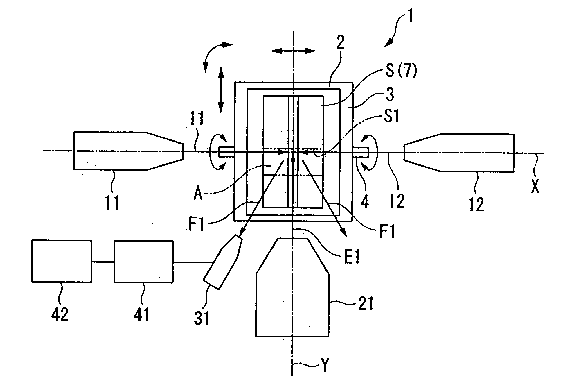
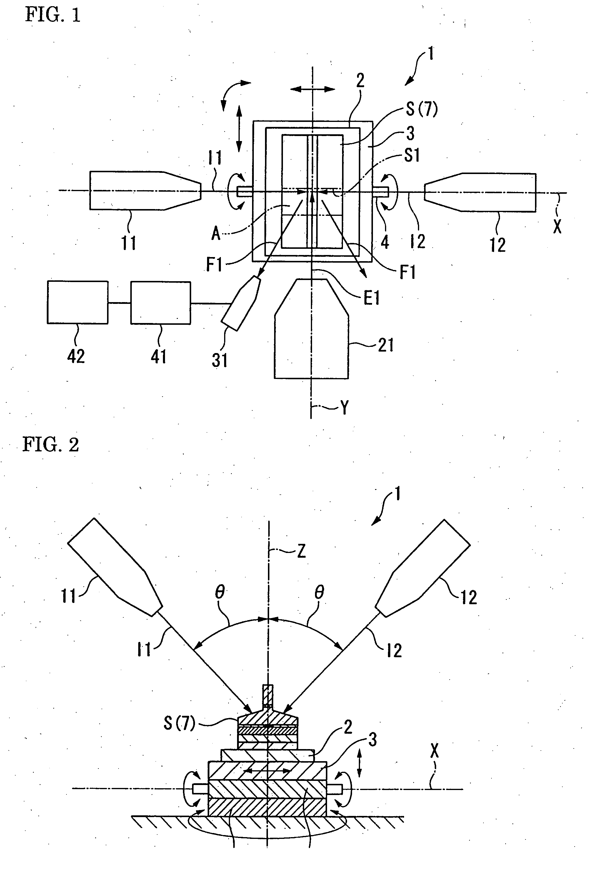
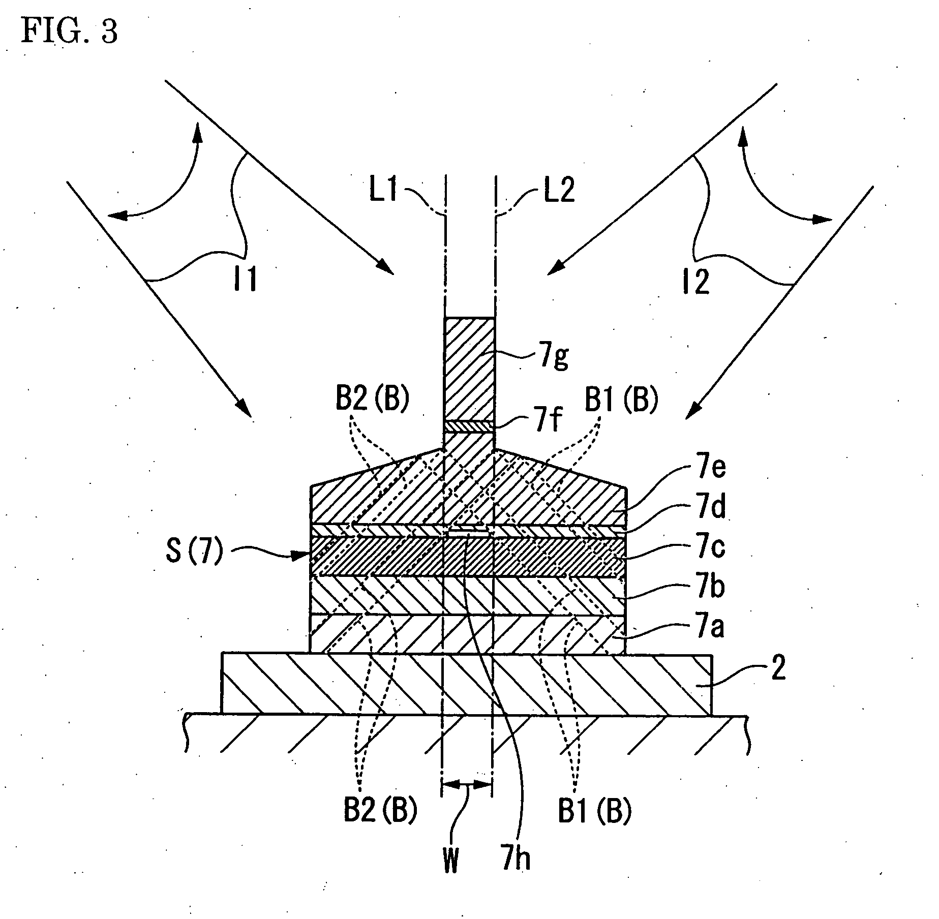
[0041]FIG. 1 through FIG. 3 show a first embodiment according to the invention. As shown by FIG. 1, a focused ion beam apparatus 1 includes a sample base 2 for mounting a sample S, and a first focused ion beam barrel 11 and a second focused ion beam barrel 12 respectively capable of emitting focused ion beams I1, I2 to the sample S mounted on the sample base 2. Both of the first focused ion beam barrel 11 and the second focused ion beam barrel 12 have ion sources of gallium ions or the like (not illustrated) inside, and are capable of emitting the focused ion beams I1, I2 by drawing out and accelerating the ion beams by applying voltages, and focusing the ion beams with electrostatic lenses (not illustrated). Further, the first focused ion beam barrel 11 and the second focused ion beam barrel 12 have deflecting electrodes (not illustrated) inside, and are capable of emitting ion beams deflected over a predetermined range by the deflecting electrodes. In addition, publicly known feat...

second embodiment

[0050]FIG. 4 and FIG. 5 show a second embodiment according to the invention. In the embodiment, members in common with the above-described embodiment are given the same notations and explanations thereof will be omitted.

[0051] As shown by FIG. 4, a focused ion beam apparatus 50 of the embodiment includes a first gas gun 51 and a second gas gun 52 for simultaneously injecting deposition gasses G1, G2 respectively in correspondence with the first focused ion beam barrel 11 and the second focused ion beam barrel 12. Here, the deposition gasses G1, G2 are, for example, W (CO) 6. By injecting the deposition gasses to the sample S along with irradiation by the focused ion beams I1, I2, a film 53 of tungsten can be formed on the surface of the sample S. Further, the deposition gasses G1, G2 are not limited to those described above, but can be selected appropriately in accordance with the material of the film 53.

[0052] According to the focused ion beam apparatus 50, the film can be formed...

third embodiment

[0053]FIG. 6 through FIG. 8 show a third embodiment according to the invention. In the embodiment, members common to members used in the above-described embodiments are attached with the same notations and an explanation thereof will be omitted.

[0054] As shown by FIG. 6 and FIG. 7, a focused ion beam apparatus 60 of the embodiment includes a first electron beam barrel 61 and a second electron beam barrel 62 for irradiating the sample S with electron beams E1, E2, and a first secondary electron detector 71 and a second secondary electron detector 72 for respectively detecting secondary electrons F1, F2 generated from the sample S by irradiating the sample S with the electron beams E1, E2. The first electron beam barrel 61 and the second electron beam barrel 62 are arranged such that the directions of the respective electron beams E1, E2 are substantially opposed to each other in a plane view thereof, and substantially orthogonal to the focused ion beams I1, I2 respectively emitted f...


PUM

PropertyMeasurementUnit
angle of inclinationaaaaaaaaaa
anglesaaaaaaaaaa

Abstract

Focused ion beam apparatus includes a sample base for mounting a sample, a three axis stage capable of moving the sample base in three directions: along two axes on a horizontal face and a vertical axis, and a first focused ion beam barrel and a second focused ion beam barrel for irradiating the sample with focused ion beams, the first focused ion beam barrel and the second focused ion beam barrel being arranged such that directions of the focused ion beams are substantially opposed to each other in a plane view thereof and are inclined in substantial line symmetry with regard to the vertical axis in a side view thereof.

Description

[0001] This application claims priority under 35 U.S.C. § 119 to Japanese Patent Application No. JP2006-036605 filed Feb. 14, 2006, the entire content of which is hereby incorporated by reference. BACKGROUND OF THE INVENTION [0002] The present invention relates to a focused ion beam apparatus for preparing a sample by irradiating the sample with a focused ion beam from a focused ion beam barrel, and a method of preparing / observing a cross section of a sample. [0003] In a background art, in steps of fabricating a semiconductor device or a thin film magnetic head with a laminated layer structure, a focused ion beam apparatus is utilized as a method of evaluating the fabricating steps. For example, by irradiating a predetermined position of a sample with a focused ion beam from a focused ion beam apparatus to carry out etching, a cross section for observation is fabricated. Further, the cross section for observation is observed by a scanning electron microscope (SEM) (refer, for exampl...

Claims


Application Information

Patent Timeline
Patent Type & Authority Applications(United States)
IPC IPC(8): H01J37/08G01N1/28G01N1/32G01N23/04G01N23/225H01J37/20H01J37/317
CPCG01N23/2251G01N23/2255H01J2237/31749H01J2237/202H01J37/3056
Inventor IWASAKI, KOUJI
Owner HITACHI HIGH TECH SCI CORP
Why Eureka
Try Eureka