Photonic crystal based rotation sensor

Active Publication Date: 2008-03-27
NORTHROP GRUMMAN GUIDANCE & ELECTRONICS
View PDF9 Cites 8 Cited by
  • Summary
  • Abstract
  • Description
  • Claims
  • Application Information

AI Technical Summary

Benefits of technology

[0013]The gyroscope can be manufactured using conventional semiconductor equipment and manufacturing techniques. The use of standard equipment to mass produce a solid state optical gyroscope offers considerable cost advantages over the conventional ring laser gyroscope and fiber optic gyroscope. The gyroscope has no moving parts making it inherently more reliable. The inherent properties of photonic crystals also allow “hairpin” turns in the ligh

Problems solved by technology

Rotation sensing devices that feature spinning mass gyroscopes have drawbacks related to wear, maintenance and start-up time.
Weight, size, precession, and cost further limit the use of a spinning mass gyroscope.
Ring laser gyros offer some improvements in cost, accuracy and reliability over classic spinning mass gyroscopes but still suffer from many drawbacks including the need for quality glass machined cavities, precision mirrors, high voltage lasers, and inert gases.
Weight, size, cost and complexity also limit the applications for which a ri

Method used


Image

  • Photonic crystal based rotation sensor
  • Photonic crystal based rotation sensor
  • Photonic crystal based rotation sensor

Examples


Embodiment Construction

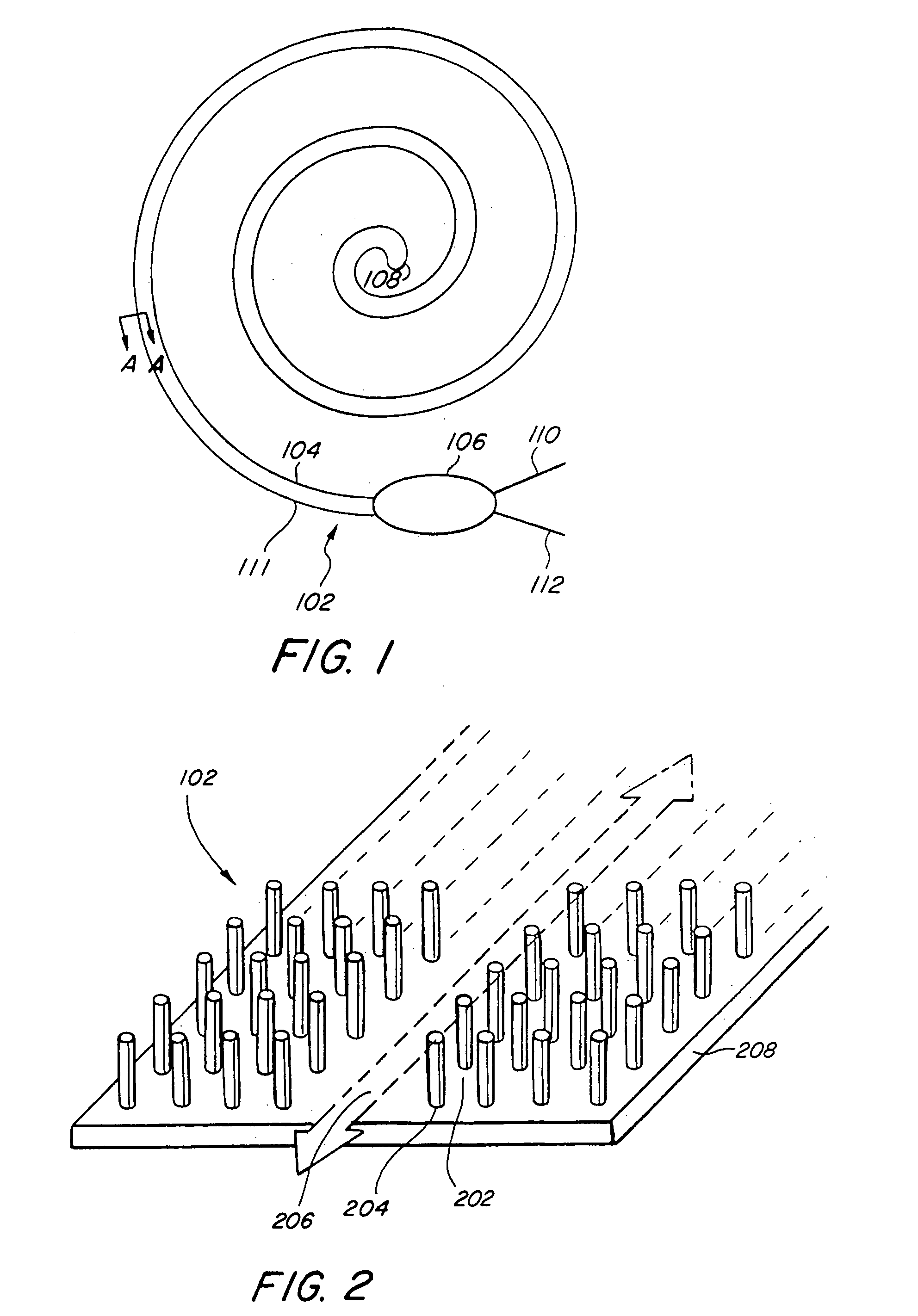
[0024]FIG. 1 shows an elongated two dimensional photonic crystal (hereinafter waveguide) 102 wrapped in a double spiral in a single plane. A first spiral 104 extends from a coupler 106 to a midpoint 108 and is characterized by a decreasing radius of curvature. A second spiral 111 extends from the coupler 106 to the midpoint 108 in a winding almost parallel to the first spiral. A first light path 110 guides coherent or laser light into the coupler. A second light path 112 guides light out of the coupler.

[0025]The first and second light paths 110, 112 are preferably composed of optical fiber for conducting coherent light. Air or an inert gas may be used for the laser light. However, any light translucent medium may be used.

[0026]Coupler 106 is a coupler acting as a beam splitter for light introduced into the waveguide 102 and a combiner for light departing the waveguide. However, the coupler may comprise a number of different optical devices such as optical beam splitters, combiners, ...


PUM


Abstract

A gyroscope having photonic crystals for sensing rotation uses the Sagnac effect to determine angular motion. The gyroscope comprises a photonic crystal capable of guiding counter-propagating light beams in a closed path. A light source, coupling, and detection apparatus permits detection of phase changes between the counter-propagating beams, thereby permitting measurement of angular rotation. The photonic crystal comprises a periodic structure of pillars and voids which creates a photonic bandgap waveguide within which light waves in the proper wavelength range propagate with low loss.

Description

BACKGROUND OF THE INVENTION[0001]1. Field of the Invention[0002]The invention relates generally to rotational sensors. More particularly, the invention relates to rotational sensors that sense rotation rate using an optical medium.[0003]2. Description of the Related Art[0004]Those concerned with the development of rotation sensors have long recognized the need for inexpensive solid state optical rotation sensors. The present invention fills this need.[0005]A classic rotation sensing apparatus consists of two spinning mass gyroscopes mounted on perpendicular axes of a three axis gimbaled platform. The gyroscopes stabilize the platform in inertial space. The angular position of the body housing the apparatus can then be measured at the gimbals. Digital computers create an alternative to the gimbaled platform, and angular position can be calculated by integrating angular rate information derived from torque measurements on spinning mass gyroscopes. Rotation sensing devices that feature...

Claims


Application Information

Patent Timeline
IPC IPC(8): G01C19/66G02B6/00
CPCG01C19/64
Inventor TAZARTES, DANIEL A.MARINO, KENNETH D.
Owner NORTHROP GRUMMAN GUIDANCE & ELECTRONICS
Why Eureka
Try Eureka