
Hand-held vital signs monitor

a vital signs monitor and hand-held technology, applied in the field of medical devices for monitoring vital signs, can solve the problems of complicated ptt-based blood pressure measurement, short ptt, and inability to accurately calculate the blood pressure in the ventricle, etc., to achieve simple, rapid, pain-free manner, and increase the effect of blood pressure calculation

Active Publication Date: 2008-03-27
SOTERA WIRELESS
View PDF64 Cites 202 Cited by
  • Summary
  • Abstract
  • Description
  • Claims
  • Application Information

AI Technical Summary

Benefits of technology

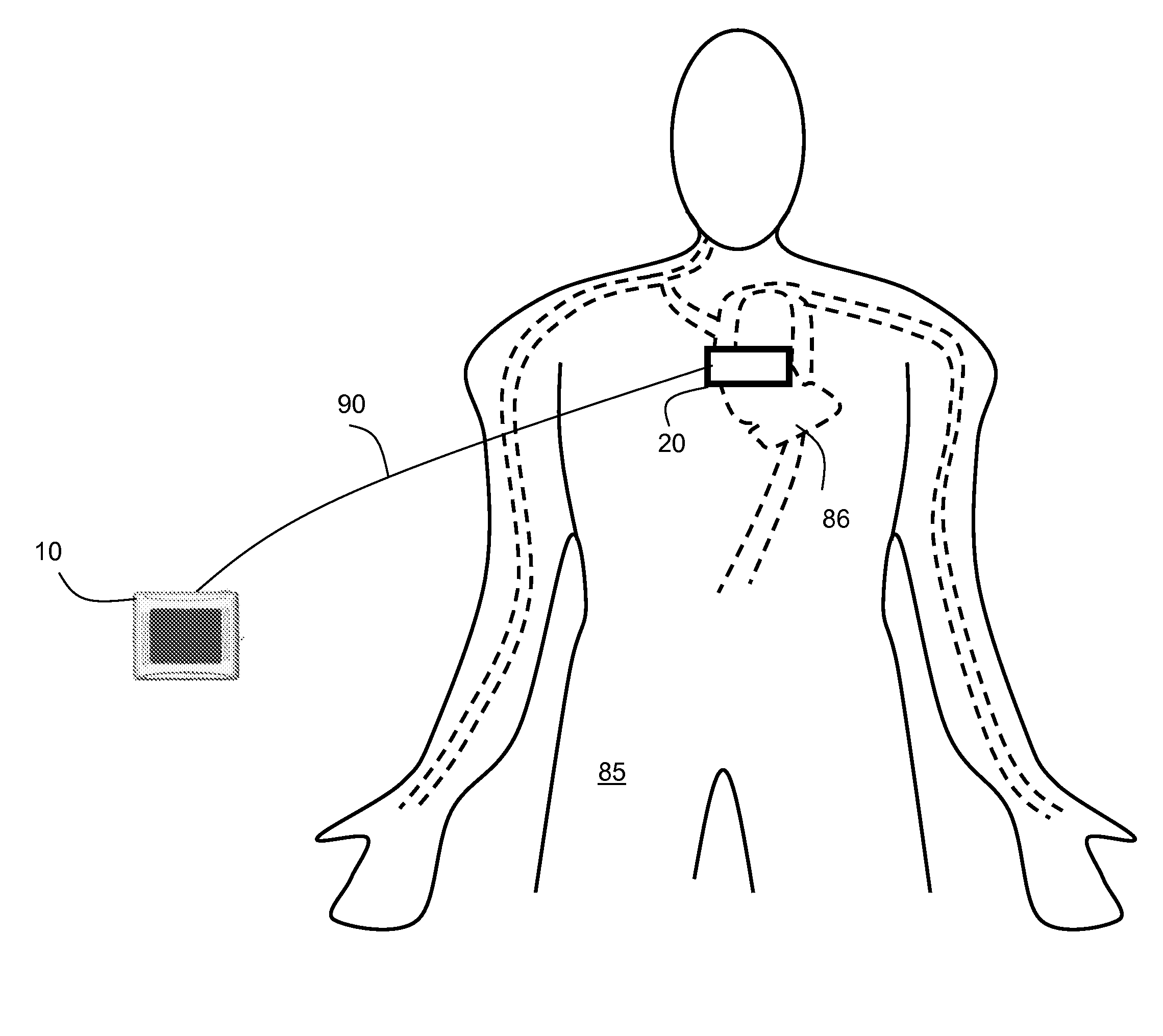
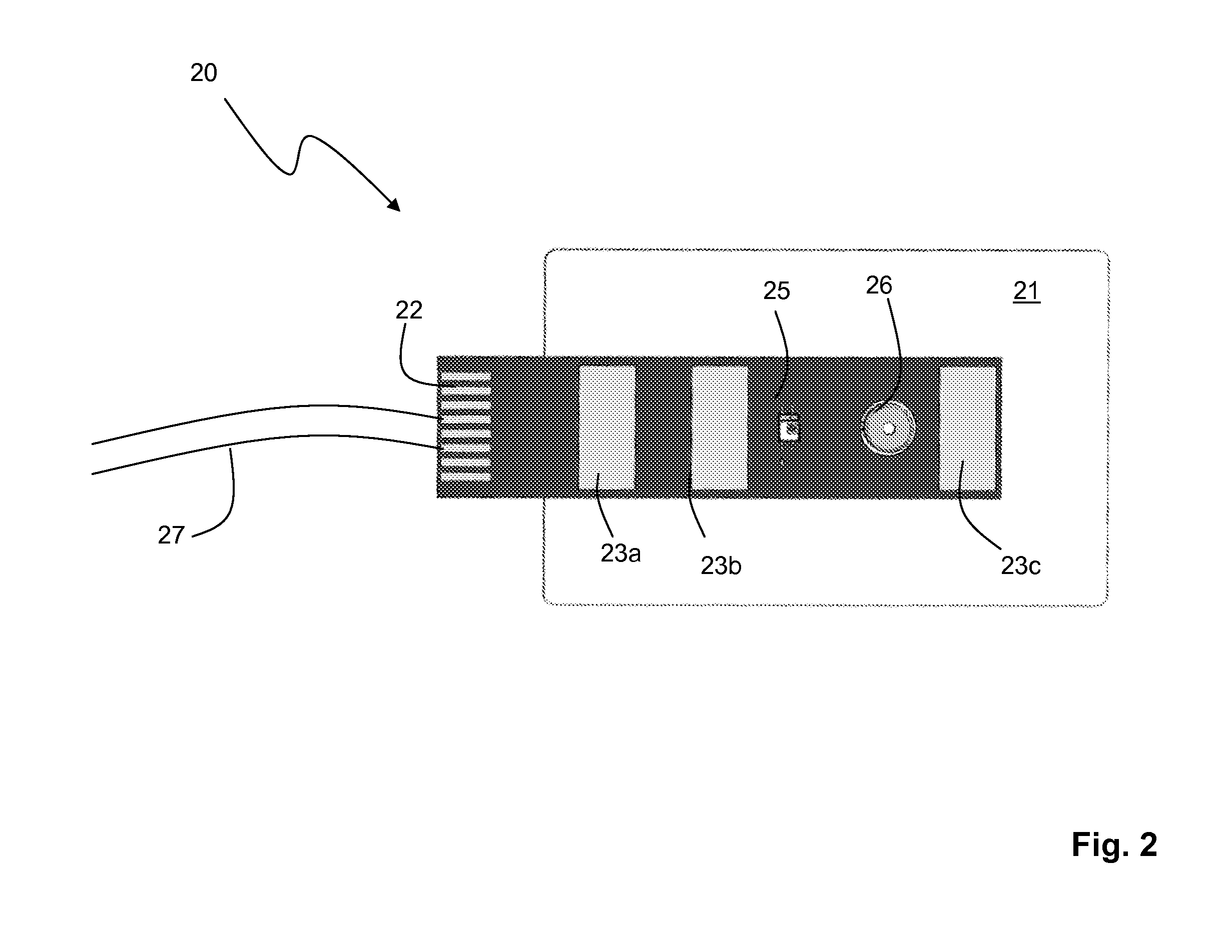
[0013]The monitor makes cuffless blood pressure measurements using a sensor that includes small-scale optical, electrical, and acoustic sensors. The sensor typically attaches to a patient's chest, just below their sternal notch. A flexible foam substrate supports the optical, electrical, and acoustic sensors and has a form factor similar to a conventional bandaid. During operation, these sensors measure, respectively, time-dependent optical, electrical and acoustic waveforms that the microprocessor then analyzes as described in detail below to determine blood pressure and other vital signs. In this way, the sensor replaces a conventional cuff to make a rapid measurement of blood pressure with little or no discomfort to the patient.
[0016]The vital signs monitor works in concert with the sensor to measure a patient's vital signs without using a convention blood pressure cuff. The patient typically wears the sensor on or just below the ‘sternal’ notch of their chest, proximal to their heart. In this location the sensor simultaneously measures, optical, electrical, and acoustic signals, which are then processed with an algorithm described below to measure blood pressure and other vital signs. The measurement is possible because: 1) the proximity of this area to the heart allows the acoustic sensor to measure the acoustic waveform; 2) an abundance of capillaries in the sternal notch, meaning the optical waveform can be measured in a reflective mode; and 3) the strong electrical activity of the heart in this area, meaning the electrical waveform can be measured with a high signal-to-noise ratio even when the electrodes are relatively close together.
[0018]To generate the electrical waveform, the electrical sensor detects first and second electrical signals with, respectively, first and second electrodes. The electrical signals are then processed (e.g. with a multi-stage differential amplifier and band-pass filters) to generate a time-dependent electrical waveform similar to an ECG. The electrical sensor typically includes a third electrode, which generates a ground signal or external signal that is further processed to, e.g., reduce noise-related artifacts in the electrical waveform. In embodiments, the electrodes are disposed on opposite ends of the substrate, and are typically separated by a distance of at least 5 cm. In other embodiments, to improve the signal-to-noise ratio, the sensor includes a third electrode connected to the electrical sensor by a cable. In other embodiments, the electrodes include an Ag / AgCl material (e.g., an Ag / AgCl paste sintered to a metal contact) and a conductive gel. Typically a first surface of the conductive gel contacts the Ag / AgCl material, while a second surface is covered with a protective layer. The protective layer prevents the gel from drying out when not in use, and typically has a shelf life of about 24 months. In still other embodiments, the electrodes are made from a conductive material such as conductive rubber, conductive foam, conductive fabric, and metal.
[0021]Once these parameters are determined, the processor analyzes them with a mathematical model to determine the user's blood pressure. For example, the processor can process one or more parameters with a linear model, characterized by a slope and a y-intercept, to relate it (or them) to a blood pressure value. Alternatively, the processor can relate one or more parameters to blood pressure using a relatively complex model, such as one that includes a polynomial, exponential, or a non-linear set of equations. Once the various parameters are related to blood pressure, several ‘sub-values’ can be determined and concatenated into a single blood pressure value using, e.g., a pre-determined weighted average. The above-mentioned models can also use calibration values, e.g. calibration values from a cuff-based system or arterial line, to increase the accuracy of the blood pressure calculation.

Problems solved by technology

Typically a high blood pressure results in a shorter PTT.
PTT-based measurements of blood pressure are complicated by a number of factors, one of which is the many time-dependent processes associated with each heartbeat that may correlate in a different way with blood pressure, or in fact may not correlate at all.
This causes the ventricle to fill with blood and increase in pressure.

Method used


Image

  • Hand-held vital signs monitor
  • Hand-held vital signs monitor
  • Hand-held vital signs monitor

Examples


Embodiment Construction

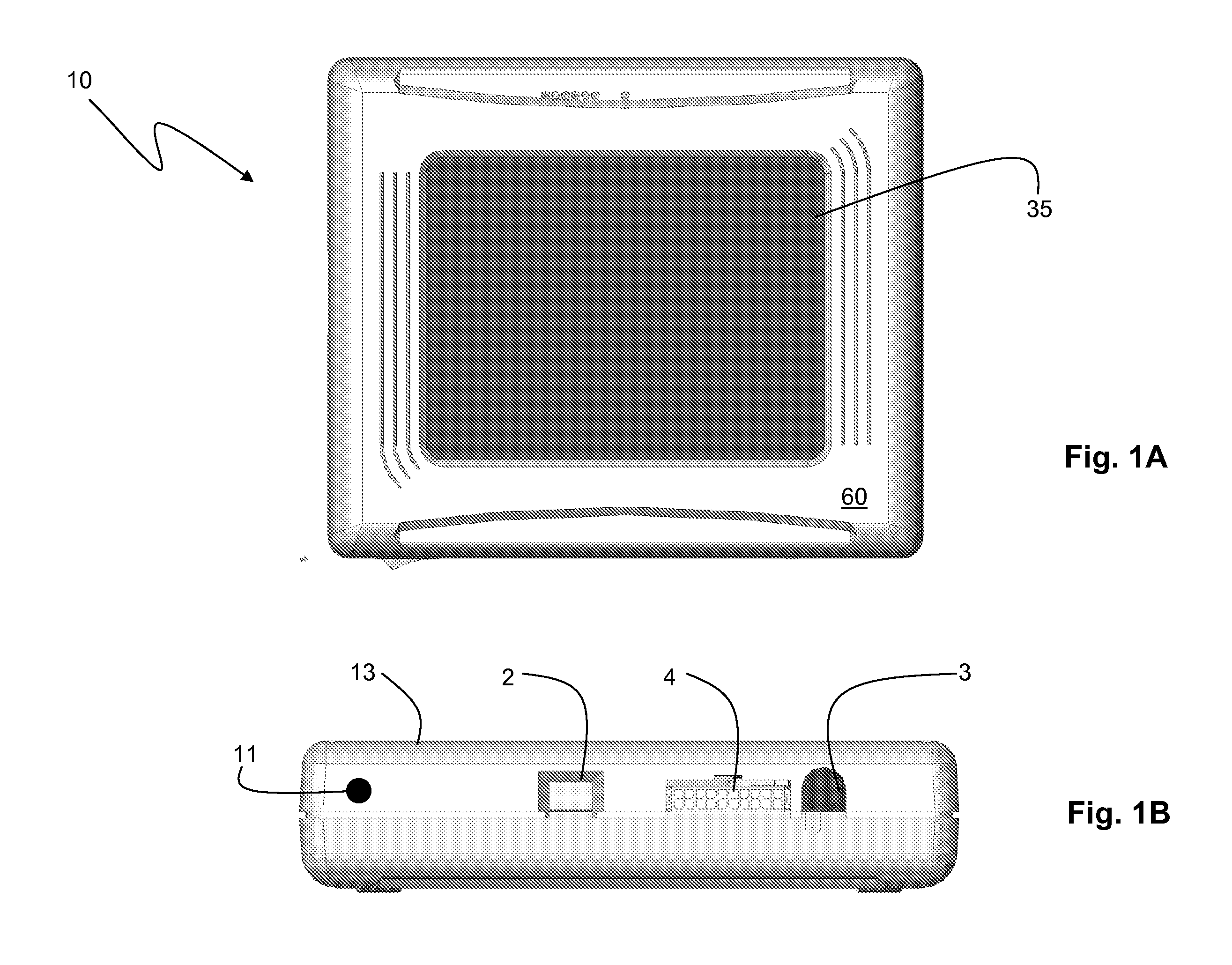
[0031]FIGS. 1A, 1B, and 2 show a vital signs monitor 10 according to the invention that attaches though a connector 4 and coaxial cable 27 to a sensor 20 that measures systolic and diastolic blood pressure, heart rate, respiratory rate, and ECG. Using a plastic stylus 11, an operator controls the vital signs monitor 10 through a GUI (shown in FIGS. 4A and 4B) that runs on a LCD / touch panel assembly 35. In this way, the operator can easily select a variety of different measurement modes to characterize a patient. For example, using the GUI and LCD / touch panel assembly 35, the user can select modes for one-time and continuous measurements in the hospital, as well as 24-hour ambulatory measurements and measurements made during patient transport outside of the hospital.

[0032]A plastic housing 60 surrounds the monitor 10 to protect its internal components. The monitor 10 additionally includes a barcode reader 2 to optically scan patient information encoded, e.g., on a wrist-worn barcode....


PUM


Abstract

The invention features a vital sign monitor that includes: 1) a hardware control component featuring a microprocessor that operates an interactive, icon-driven GUI on an LCD; and, 2) a sensor component that connects to the control component through a shielded coaxial cable. The sensor features: 1) an optical component that generates a first signal; 2) a plurality electrical components (e.g. electrodes) that generate a second signal; and, 3) an acoustic component that generates a third signal. The microprocessor runs compiled computer code that operates: 1) the touch panel LCD; 2) a graphical user interface that includes multiple icons corresponding to different software operations; 3) a file-management system for storing and retrieving vital sign information; and 4) USB and short-range wireless systems for transferring data to and from the device to a PC.

Description

CROSS REFERENCES TO RELATED APPLICATION[0001]Not ApplicableSTATEMENT REGARDING FEDERALLY SPONSORED RESEARCH OR DEVELOPMENT[0002]Not ApplicableBACKGROUND OF THE INVENTION[0003]1. Field of the Invention[0004]The present invention relates to medical devices for monitoring vital signs, e.g. blood pressure.[0005]2. Description of the Related Art[0006]Pulse transit time (‘PTT’), defined as the transit time for a pressure pulse launched by a heartbeat in a patient's arterial system, has been shown in a number of studies to correlate to both systolic and diastolic blood pressure. In these studies PTT is typically measured with a conventional vital signs monitor that includes separate modules to determine both an electrocardiogram (ECG) and pulse oximetry. During a PTT measurement, multiple electrodes typically attach to a patient's chest to determine a time-dependent ECG characterized by a sharp spike called the ‘QRS complex’. This feature indicates an initial depolarization of ventricles w...

Claims


Application Information

Patent Timeline
Patent Type & Authority Applications(United States)
IPC IPC(8): A61B5/04A61B5/332
CPCA61B5/02055A61B5/021A61B5/08A61B5/1112A61B5/14552A61B5/7435A61B5/6823A61B2562/166A61B5/029A61B5/02007A61B5/0082A61B5/04085A61B5/0404A61B5/04014A61B5/7475A61B5/6832A61B5/14551A61B5/044A61B5/04012A61B7/04A61B5/0205A61B5/0022A61B5/002A61B5/0006A61B5/0402A61B5/02125A61B2562/063G16H40/67A61B5/327A61B5/332A61B5/259A61B5/282A61B5/316A61B5/339
Inventor BANET, MATTHEW JOHNTHOMPSON, MICHAEL JAMESZHOU, ZHOUVISSER, HENKFLEMING, ADAM MICHAELDHILLON, MARSHAL SINGHTERRY, ANDREW STANLEY
Owner SOTERA WIRELESS
Learn More