Plasma etching apparatus and plasma etching method

a technology of plasma etching and plasma, which is applied in the direction of electrical equipment, basic electric elements, semiconductor/solid-state device manufacturing, etc., can solve the problems of increased product defects, non-etching portions, and deterioration of throughput, so as to improve the value of etching, prevent the flow of smooth gas, and increase the speed response

Inactive Publication Date: 2008-04-03
HITACHI HIGH-TECH CORP
View PDF8 Cites 16 Cited by
  • Summary
  • Abstract
  • Description
  • Claims
  • Application Information

AI Technical Summary

Benefits of technology

[0015]The object of the present invention is to provide a plasma etching apparatus and a plasma etching method capable of switching gas flow rates and gas pressures smoothly with superior reproducibility and at high speed in a shower plate structure or a nozzle structure.
[0016]The present inventors have examined pressure undershoot, and discovered that undershoot is caused by back flow of gas, and that there are two mechanisms related to the back flow of gas. The first mechanism is described with reference to FIG. 29. In a shower plate structure or a nozzle structure, the inner diameter of the holes 11 for introducing gas into the vacuum processing chamber 6 is smaller than the inner diameter of the processing gas line 8, by which the gas flow is somewhat hindered. Thus, the pressure Po in the processing gas line 8 becomes significantly higher than the pressure P1 in the exhaust gas line 9. At the instant the valve 113 is opened and the valve 114 is closed, the pressure in the area of the gas pipe 115 surrounded by the valve 113, the valve 114 and the MFC 112 is P1, which is smaller than the pressure Po of the processing gas line 8, so that back-flow of gas occurs from the processing gas line 8 to the gas pipe 115. This back-flow phenomenon caused by the first mechanism occurs with high reproducibility.

Problems solved by technology

However, this method had two drawbacks.
One is the deterioration of throughput.
Another problem is the increase of product defects.
Therefore, even when the particles are removed by wet cleaning process, the non-etched portions remain and become the cause of product defects.
However, even by adopting this method, it is impossible to avoid deterioration of throughput since the time required for switching gases is not reduced.
However, in a gas switching system normally used for etching, the response property in switching gases is not good.
At this time, the processing chamber pressure also overshoots, and it takes a few seconds for the pressure to become steady.
Thus, another drawback occurs in that etching reproducibility is deteriorated.
Furthermore, in the actual etching apparatus, since a shower plate structure or a nozzle structure for injecting gas through small holes is adopted as the gas supplying mechanism, the response property becomes even more complex.
However, the high-speed gas flow rate control system disclosed in patent document 1 does not take into consideration the effect of shower plate structures or nozzle structures.
In addition, it has been discovered that the degree of undershoot had no reproducibility, and that large and small undershoots occurred.
In other words, it has been discovered that the prior art arrangement had the drawbacks of (1) undershoot and (2) low response.
Continuous discharge was performed in the above arrangement, and it has been discovered that the arrangement had the drawbacks of (1) particles adhering to the wafer by the sudden drop of pressure immediately after switching conditions by which plasma is extinguished, and (2) gases not being switched completely in a short time by which it becomes difficult to achieve a stable etching property.

Method used


Image

  • Plasma etching apparatus and plasma etching method
  • Plasma etching apparatus and plasma etching method
  • Plasma etching apparatus and plasma etching method

Examples


embodiment 1

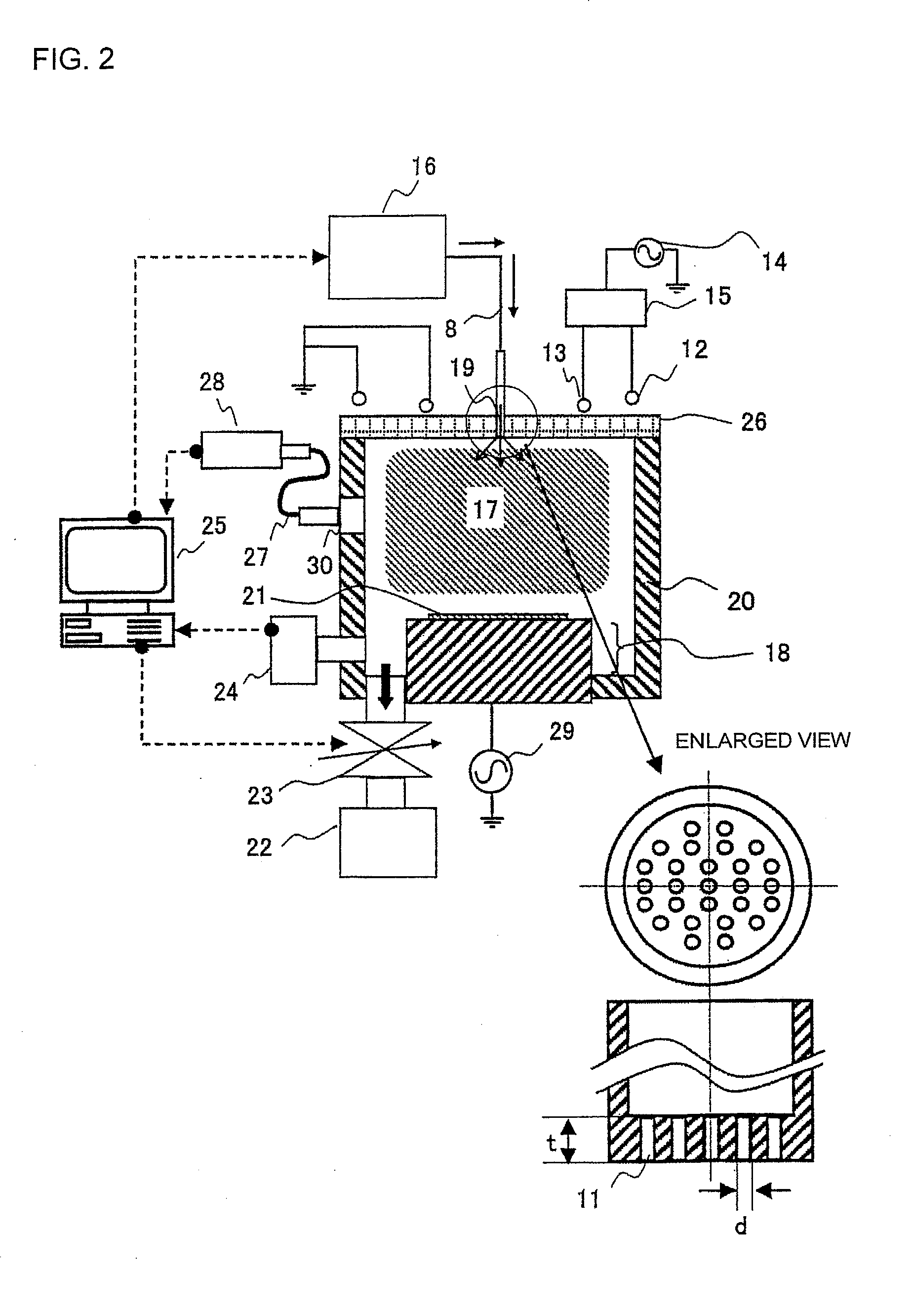
[0054]The configuration of an apparatus according to one preferred embodiment of the present invention is illustrated in FIG. 2. In the apparatus of FIG. 2, etching gas is supplied from a gas supply unit 16 via a processing gas line 8 and a gas feed mechanism 19 into a vacuum processing chamber 20, and an RF power of 13.56 MHz for example is applied from a discharging RF power supply 14 via an antenna coil 13 and an antenna coil 12 disposed outside a dielectric window 26 made of alumina, so as to generate inductively-coupled plasma 17 from the etching gas. A power distributor 15 is disposed between the antenna coils 12, 13 and the discharging RF power supply 14 for controlling the ratio of power supply to the antenna coils 12 and 13, by which the distribution of plasma generation can be controlled. Etching is performed by irradiating the plasma 17 on a sample 21 placed on a sample stage 18. A bias RF power supply 29 is connected to the sample stage 18, and the sample 21 can be etche...

embodiment 2

[0070]A three step etching as illustrated in FIG. 10 is performed using the configuration of embodiment 1. At this time, a phenomenon occurs in which plasma is extinguished due to the occurrence of pressure undershoot immediately after step 1 and pressure overshoot immediately after step 2, as illustrated in FIG. 11. Thus, the prevent inventors have examined the cause of occurrence of such undershoot and overshot, and considered a method for reducing the same.

[0071]According to the present system, since the response of gas flow rate is high and the gas flow rate is changed rapidly, a pressure control mechanism having a slow response cannot follow such change. This is considered to have caused the undershoot and overshoot illustrated in FIG. 11. In order to solve this problem, the present inventors have examined methods to change the gas flow rate in steps.

[0072]As illustrated in FIG. 12, the flow rate of MFC 112 is set to 150 sccm for the first 1.0 s of step 2, and thereafter, the f...

embodiment 3

[0074]FIG. 13 illustrates an arrangement in which the gas switching system of embodiment 1 is applied to a microwave etching apparatus. In the apparatus of FIG. 13, the etching gas is supplied from a gas supply unit 16 via a gas reservoir 10 disposed in the interior of a dielectric window 26 formed of quartz and through multiple holes (a shower plate structure) disposed on the side facing the vacuum processing chamber of the dielectric window 26 and into the vacuum processing chamber. Further, microwaves generated via a magnetron 53 is supplied via a waveguide 54, a cavity resonator 55 and a dielectric window 26 into the vacuum processing chamber, wherein a plasma 17 is generated by the interaction between the microwaves and the magnetic field created via coils 56. In the apparatus, the volume of the vacuum processing chamber is 150 L, which is relatively large so as to improve the stability of pressure control. The other arrangements are the same as that of embodiment 1. As an exam...


PUM

PropertyMeasurementUnit
depthaaaaaaaaaa
diameteraaaaaaaaaa
lengthaaaaaaaaaa

Abstract

The invention provides a method for overcoming the drawbacks of deteriorated throughput, deteriorated reproducibility and plasma discharge instability when continuous discharge is performed during multiple steps of plasma etching. The present invention provides a gas switching method for switching from gas supply source 101 to gas supply source 111, wherein the gas supply source 101 is switched to gas supply source 111 by opening a valve 114 in advance, setting a flow rate of MFC 112 to a flow rate used in the subsequent step, letting the gas supply source 111 to flow toward an exhaust means 5, and closing the valve 114 simultaneously when opening the valve 113, wherein a volume V1 of an area of a gas pipe 115 surrounded by the valve 113, the valve 114 and the MFC 112 is set sufficiently smaller than a volume Vo from the shower plate to the valve 113 including a gas reservoir 10 and a processing gas line 8. The present arrangement enables to prevent the occurrence of pressure undershoot and to solve the problem of discharge instability.

Description

[0001]The present application is based on and claims priority of Japanese patent application No. 2006-271362 filed on Oct. 3, 2006, the entire contents of which are hereby incorporated by reference.BACKGROUND OF THE INVENTION[0002]1. Field of the Invention[0003]The present invention relates to a plasma etching apparatus for processing semiconductor substrates such as semiconductor wafers, and a plasma etching method utilizing the apparatus.[0004]2. Description of the Related Art[0005]We will describe the transition regarding the art of plasma etching used for processing gates in semiconductor devices. Until the early 1990s, a single layer Poly-Si film was used for gate electrodes. Therefore, the gates were mainly processed under a single etching condition. In the late 1990s, when gates having a multi-layered structure of different materials were introduced, it has become difficult to process the gates under a single etching condition, and from then on, methods for processing gates v...

Claims


Application Information

Patent Timeline
Patent Type & Authority Applications(United States)
IPC IPC(8): H01L21/306
CPCH01L21/3065H01L21/32137H01L21/32136H01L21/31116
Inventor KOFUJI, NAOYUKIAKIYAMA, HIROSHISATOU, KOUHEI
Owner HITACHI HIGH-TECH CORP
Why Eureka
Try Eureka