Rotary electric apparatus having rotor with field winding inducing current therethrough for generating magnetic field

a rotary electric and field winding technology, applied in the direction of dynamo-electric converter control, magnetic circuit rotating parts, magnetic circuit shape/form/construction, etc., can solve the problem of large ripples in generated torque (torque ripples), and achieve the effect of preventing an increase in the magnetic resistance of the rotor cor

Active Publication Date: 2008-04-03
DENSO CORP
View PDF12 Cites 39 Cited by
  • Summary
  • Abstract
  • Description
  • Claims
  • Application Information

AI Technical Summary

Benefits of technology

[0014] A second object of the present invention is to provide rotary electric machines, such as field winding type synchronous machines, which are able to prevent an increase in the magnetic resistance of the rotor core, while still securing field windings to the rotor and providing an improved work when assembling the field windings with the rotor.

Problems solved by technology

This current flow will cause larger ripples in the currents flowing through the rotor windings, causing larger ripples in the generated torque (torque ripples).

Method used


Image

  • Rotary electric apparatus having rotor with field winding inducing current therethrough for generating magnetic field
  • Rotary electric apparatus having rotor with field winding inducing current therethrough for generating magnetic field
  • Rotary electric apparatus having rotor with field winding inducing current therethrough for generating magnetic field

Examples


first embodiment

[0072] Referring to FIGS. 1-19, a rotary electric apparatus according to a first embodiment of the present invention will now be described.

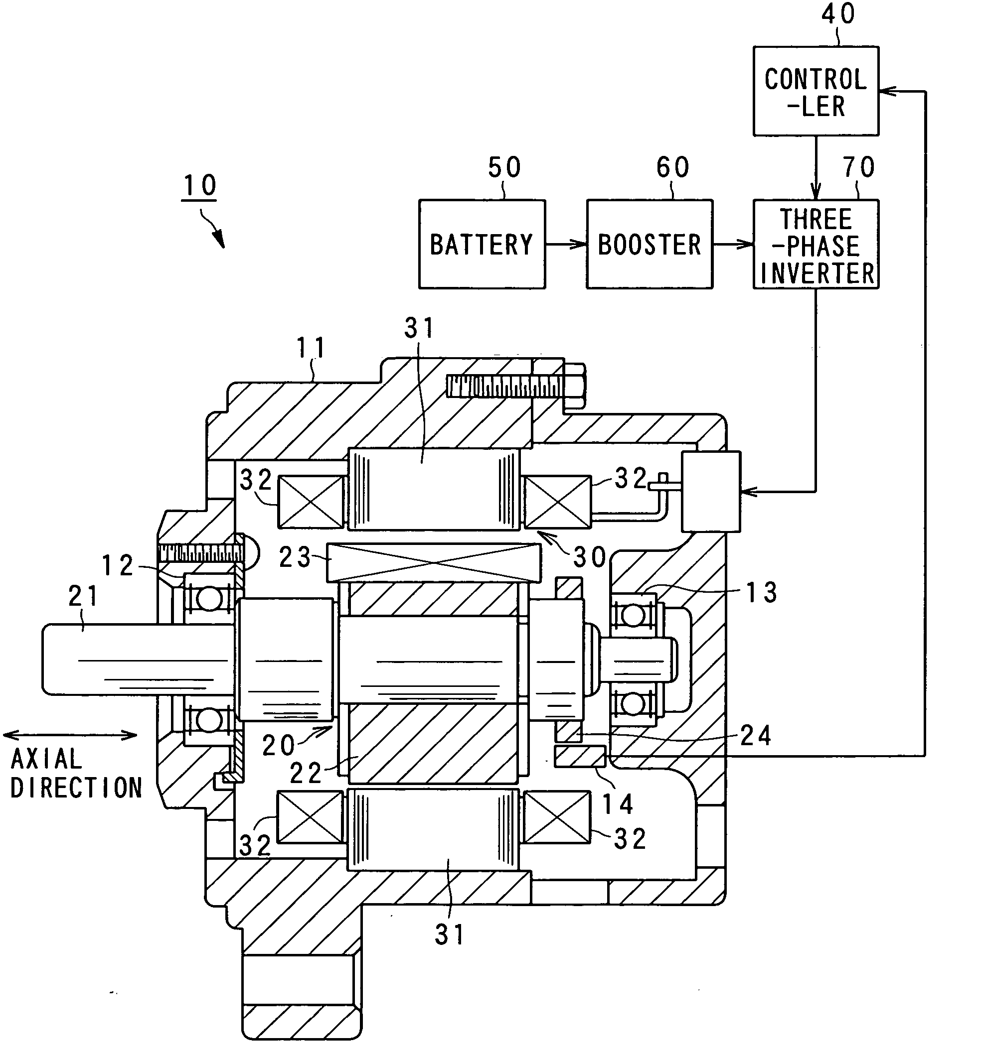
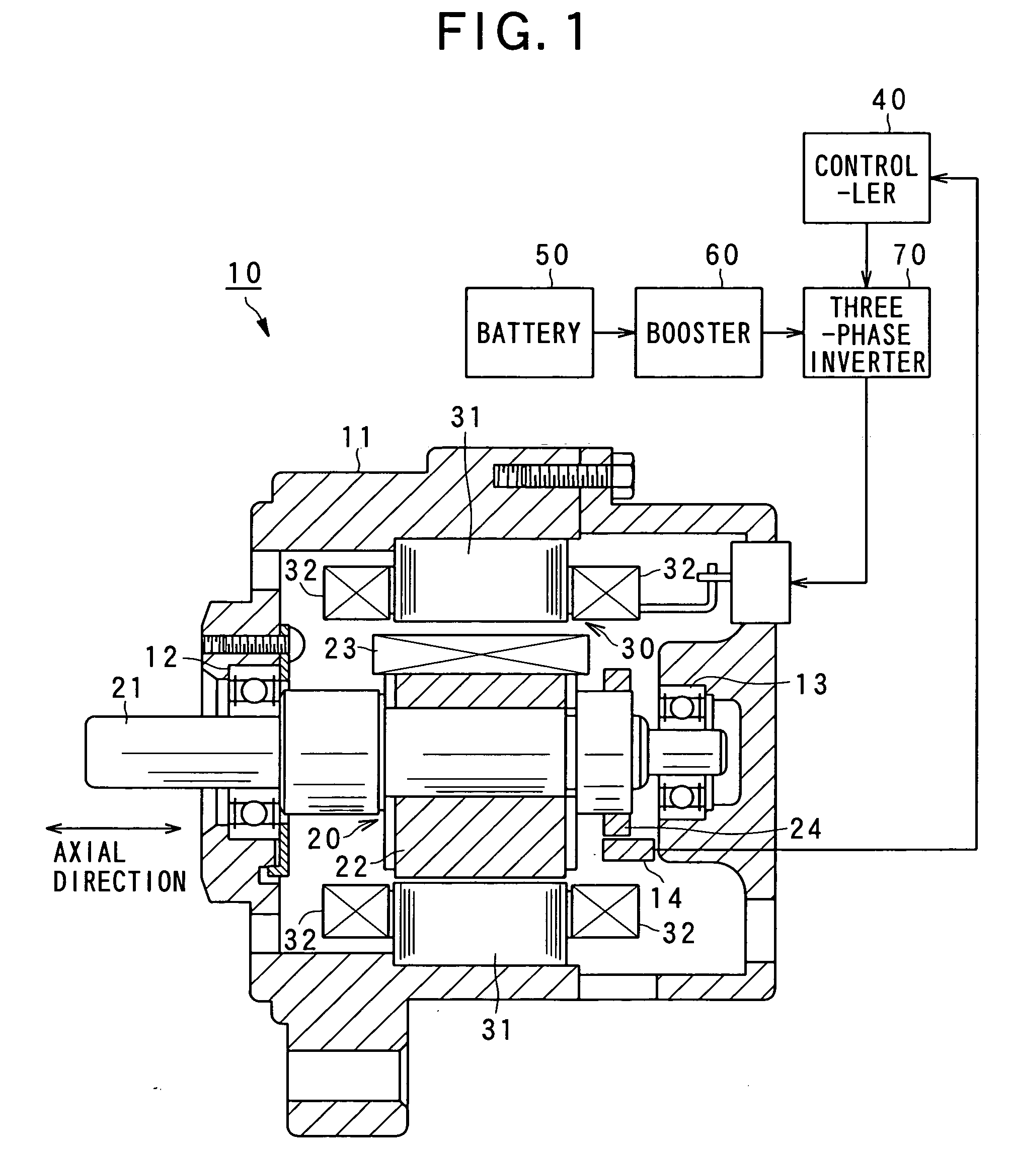
[0073]FIG. 1 shows the configuration of a rotary electric apparatus according to the present invention. The rotary electric apparatus includes a “synchronous motor (which is a field winding type of synchronous motor)”10 according to a first embodiment. As shown, the synchronous motor 10 is equipped with a housing 11, a rotor 20, and a stator 30.

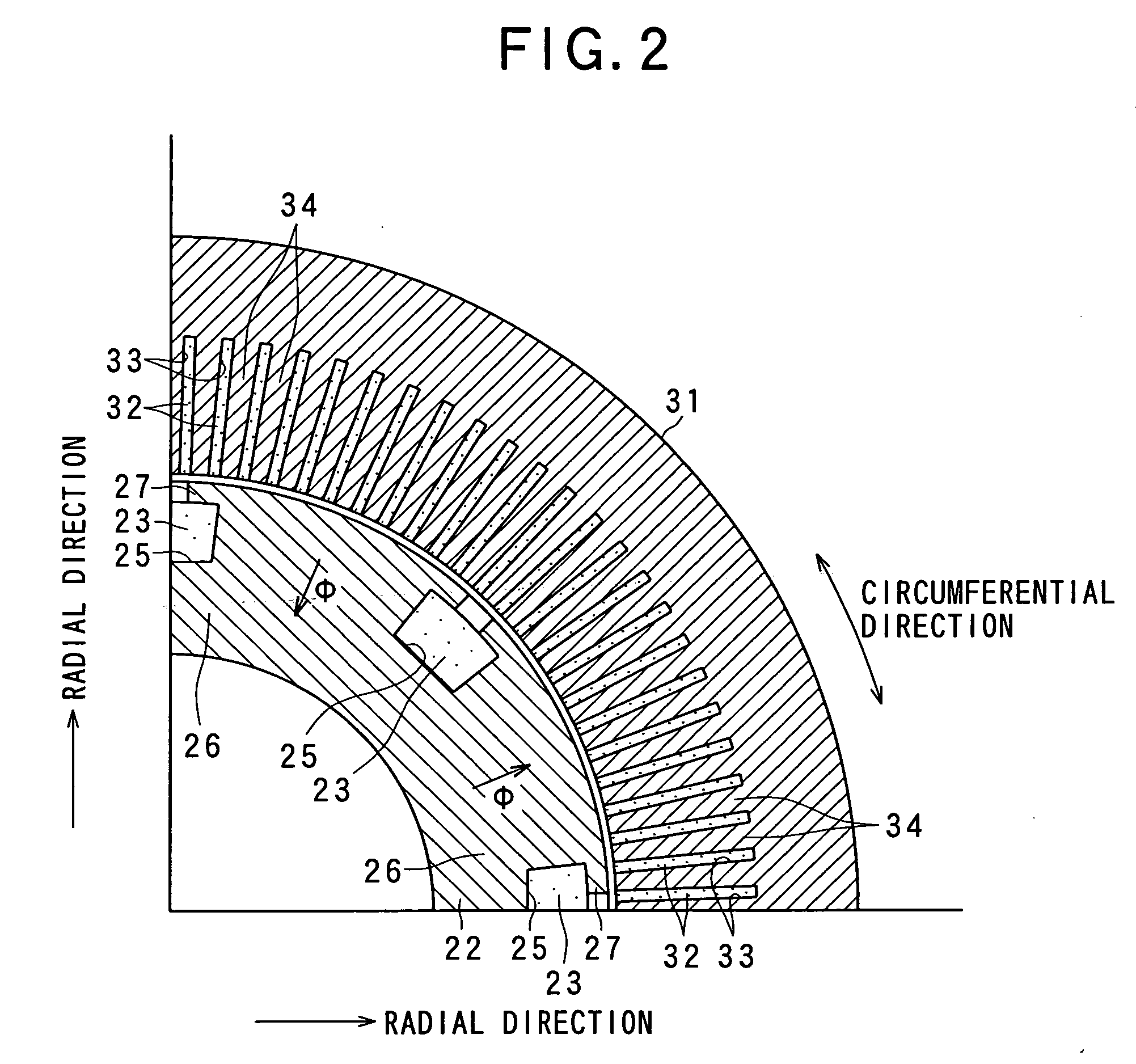
[0074] Of these components, the rotor 20 is provided with a shaft 21, a rotor core 22, and a rotor coil 23. The shaft 21 is rotatably supported to the housing 11 with a pair of bearings 12 and 13. The shaft 21 is a cylindrical member having a predetermined length along which an axial direction can be defined, whereby a radial direction can be defined as directions perpendicular to the axial direction and a circumferential direction around the shaft 21 (refer to FIGS. 1 and 2). These primary directions ca...

second embodiment

[0124] Referring now to FIGS. 23-34, a “synchronous motor 10A” (, which is a field winding type of synchronous machine) according to a second embodiment of the present invention will be described.

[0125] In the second embodiment and subsequent embodiments and modifications, the components which are the same or identical as or to those in the first embodiment are given the same reference numerals for the sake of simplifying the description.

[0126]FIG. 23 shows a circuit diagram of the motor 10A according to the second embodiment. As shown, the equivalent circuit of the rotor 20 is expressed in a different way from that in the first embodiment.

[0127] In the rotor 20, the rotor coil 23 has no electrical connection with the battery 50 and is short-circuited by the diode 28. The rotor coil 23 has an inductance L. Both the rotor coil 23 and the diode 28 have a resistance component which can be denoted by a resistor 29 which is different from those elements 23 and 28, the resistance of wh...

third embodiment

[0188] Referring now to FIGS. 35-41, a field-winding type of synchronous machine with armature windings being powered, which is based on the present invention, will now be described.

[0189] In the third embodiment, the field-winding type of synchronous machine is reduced into practice as an on-vehicle “generator motor.” The vehicle on which the generator motor is mounted is for example a hybrid electric vehicle with a battery and an engine both serving as drive sources, an electric vehicle with a battery serving as a drive source, and a fuel-cell electric vehicle.

[0190]FIG. 36 shows a section of the generator motor 10B according to the present embodiment. The generator motor is provided with a stator 110 with a stator core 111, stator coils (i.e., stator windings) 112 wound in the stator core 111, a rotor 120 with a rotor core 121, a rotor coil (i.e., field winding) 122 wound in the rotor core 121, a rotor shaft 123, frames 131 and 132, and a position sensor 133.

[0191] The stator ...


PUM


Abstract

A rotary electric apparatus comprise a synchronous machine of field winding type, an inverter, a DC power supply, a current flow regulator, and a controller. The DC power supply outputs first voltage of a first voltage value and second voltage of a second voltage value higher than the first voltage value. The current flow regulator regulates directions of currents flowing through a field winding by rotor exciting currents into one way, the current flow regulator being electrically connected to the field winding. The controller controls the inverter such that the inverter produces armature currents consisting of synchronized currents producing rotating fields depending on a rotating position of a rotor and rotor exciting currents different in waveforms from the synchronized currents and superposed on the synchronized currents. At least the rotor exciting currents are powered on a second voltage from the DC power supply.

Description

CROSS REFERENCES TO RELATED APPLICATIONS [0001] The present application relates to and incorporates by reference Japanese Patent Applications Nos. 2006-265418 filed on Sep. 28, 2006, 2006-292548 filed on Oct. 27, 2006, and 2007-9105 filed on Jan. 18, 2007. BACKGROUND OF THE INVENTION [0002] 1. Field of the Invention [0003] The present invention relates to a rotary electric apparatus, and in particular, to a synchronous machine such as synchronous motor generator. [0004] 2. Description of the Related Art [0005] There are a variety of types of rotary electric apparatuses and one type of such apparatuses is called synchronous machines. The synchronous machine is provided with a stator and a rotor, in which AC armature currents flow through the stator so that a rotary magnetic field is produced to rotate the rotor synchronously with the rotary magnetic field. As the rotors of the synchronous machines, there are known a magnet type rotor, a field winding type rotor, a reluctance type rot...

Claims


Application Information

Patent Timeline
Patent Type & Authority Applications(United States)
IPC IPC(8): H02P6/08H02K1/24H02K19/00H02K9/19H02P27/08
CPCH02K21/042H02P27/08H02P9/009H02P25/03
Inventor SEGUCHI, MASAHIRO
Owner DENSO CORP
Why Eureka
Try Eureka