Dynamic Liquid Crystal Gel Holograms

a liquid crystal gel and hologram technology, applied in the field of dynamic holograms, can solve the problems of complex material manufacturing and lack of flexibility for in situ liquid crystal control, and achieve the effects of high transparency, simple fabrication, and easy operation

Inactive Publication Date: 2008-04-17
KONINKLIJKE PHILIPS ELECTRONICS NV
View PDF2 Cites 69 Cited by
  • Summary
  • Abstract
  • Description
  • Claims
  • Application Information

AI Technical Summary

Benefits of technology

[0004] It would be advantageous if it was possible to provide improved dynamic holographic elements having simple fabrication, easy operation, high transparency, low diffraction in an off-state, high diffraction efficiency in an on-state, and well defined birefringent properties.
[0007] The inventors of the present invention have found that by using an anisotropic LC pre-gel mixture instead of an isotropic pre-PDLC mixture, a holographic LC gel element that perform differently than holographic PDLC elements can be produced. The production involves a two-step illumination process, which results in new and surprising characteristics of the holographic element.
[0015] LC pre-gel mixtures can be photo-polymerized by illuminating the material with polymerizing radiation, typically ultraviolet (UV) light. During polymerization, networks of cross-linked polymer chains are formed which reduces the tendency of the LC molecules to align in an exterior electric field. In the present context, polymerizing as a verb means to undergo or be subject to polymerization and, as an adjective, means the ability to cause or induce polymerization in a polymerizable medium.
[0028] In a preferred embodiment, the LC phase further comprises non-linear photo absorber having a nonlinear absorption of the polymerizing light, typically a UV absorber or a dye. The nonlinear absorption component shows a non-linear absorption behavior and above certain intensity, absorption decreases. Thereby, in the most ideal case the nonlinear absorption component reduces the amount of radiation impinging the photoinitiator in the low intensity regions while leaving the high intensity region unaffected. This will increase the effective intensity contrast between lowly and highly illuminated regions and provides high diffraction efficiency in the system. The non-linear photo absorber may e.g. be a photochromic or photo bleaching dye. Examples of such dyes can be found in FIG. 19A through F; salicylidene-anilines (A), stillbenes (B), azo compounds (C) and other photochromic materials such as Spiropyrans (D), fulgides (E) the diarylethenes (F) are also suitable. In these figure general structures of the dyes are shown. R represents subtitutions.
[0047] Due to the anisotropy prior to polymerization, all regions are aligned in the electric field off-state in the LC gel element of the present invention. Upon application of an electrical field, different regions change orientation differently. This provides the advantage that the element will show polarization dependence or birefringence at all times in all states, regardless of the electric field. This is often a requirement in optical set-ups.

Problems solved by technology

Unfortunately, these materials are complex to manufacture and do not offer flexibility for in situ control over liquid crystal domain size, shape, density, or ordering.

Method used


Image

  • Dynamic Liquid Crystal Gel Holograms
  • Dynamic Liquid Crystal Gel Holograms
  • Dynamic Liquid Crystal Gel Holograms

Examples


Embodiment Construction

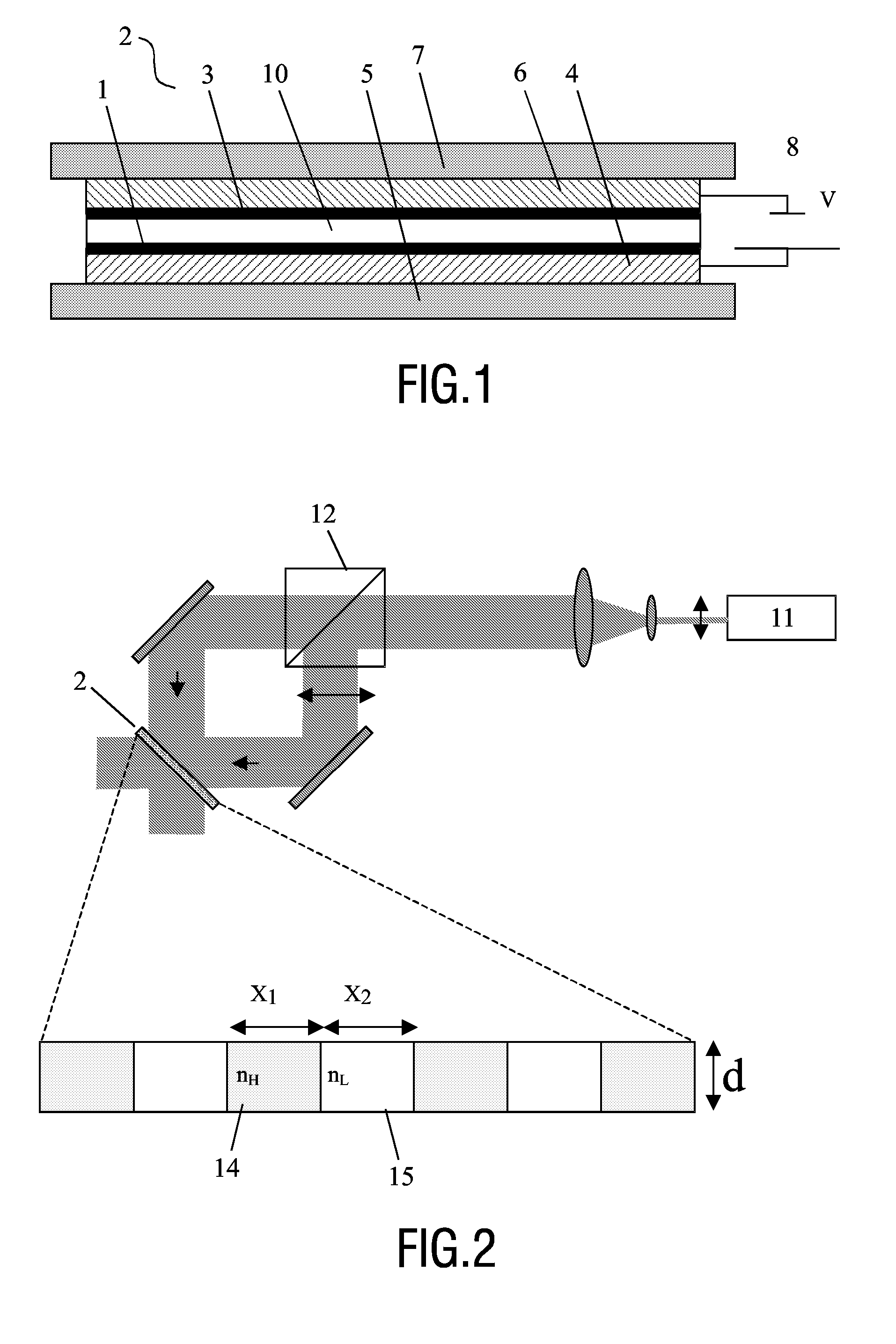
[0068]FIG. 1 shows a general layout of a cell 2 used for holographic liquid crystal elements according to the invention. The element comprises a transparent cathode 4 and a transparent anode 6 electrically connected to a power supply 8 for creating an electrical field between these. The electrodes are held by transparent substrates 5 and 7 and encompass a LC gel phase or a LC pre-gel mixture 10. Macroscopic orientation within the pre-gel mixture is induced by orientation layers 1 and 3. These layers are usually made of uniaxially rubbed polymer such as polyimide for planar orientation. In order to induce perpendicular orientation of molecules with respect to surface the orientation layers can chosen to be surfactants. The various kinds of applicable layers are known by those skilled in the art.

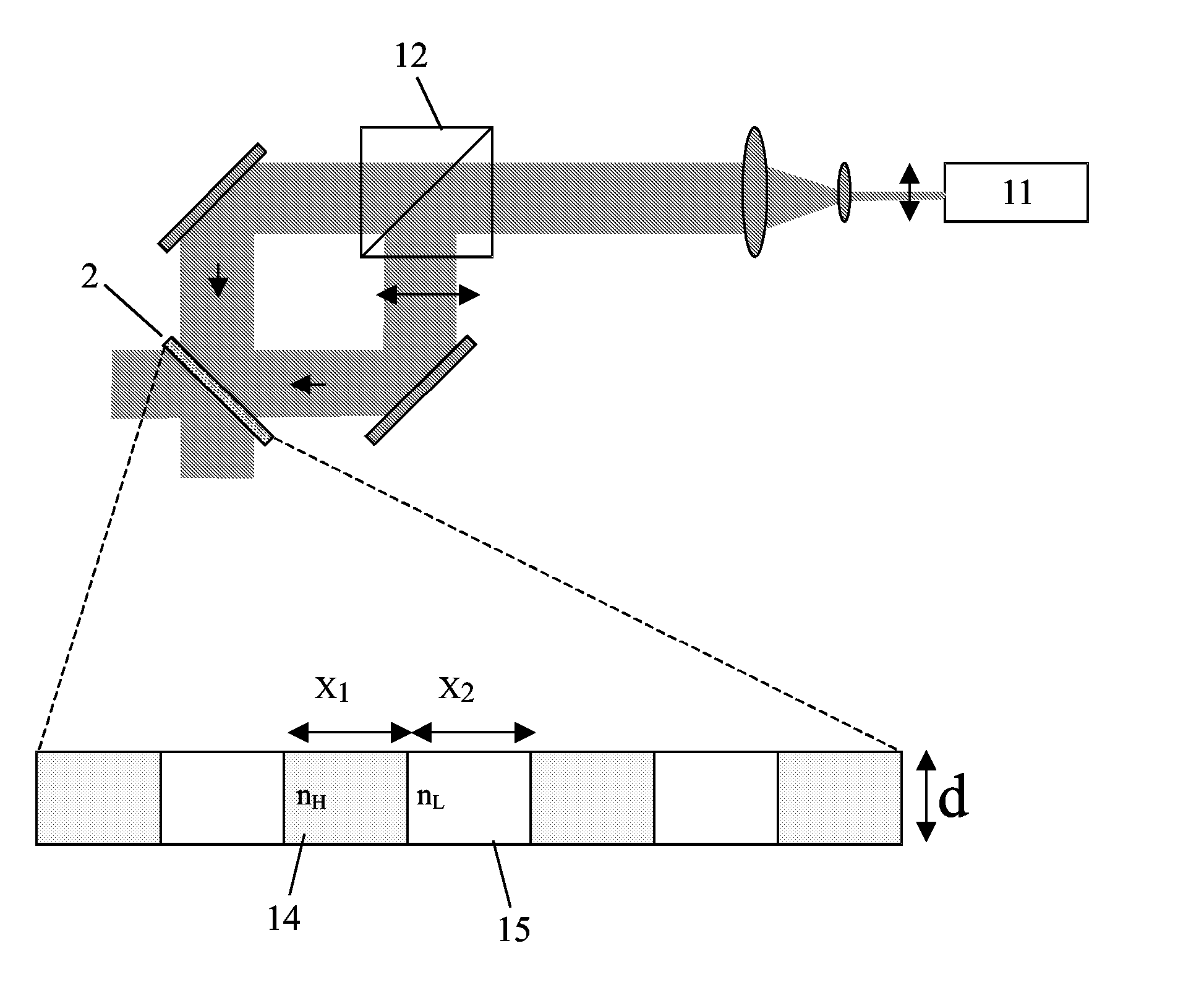
[0069]FIG. 2 illustrates a simple layout for forming a holographic element. Here, in a first step, a beam from a laser 11 is split by a polarizing beam splitter 12 and then brought together t...


PUM

PropertyMeasurementUnit
network densityaaaaaaaaaa
electric fieldaaaaaaaaaa
threshold switching voltageaaaaaaaaaa

Abstract

A dynamic hologram is formed in anisotropic liquid crystal (LC) gel materials. By applying an electric field, the orientation of part of the liquid crystals can be altered and the hologram can be turned on and off. Using LC gels allows for holographic elements with no diffraction in the voltage off state so that the hologram appears only during application of an electric field. Also, the anisotropic LC gels maintain polarization dependence. The dynamic holograms are suitable in e.g. dynamic holographic optical components whereby an optical function can be included / excluded in a beam path without introducing or removing elements.

Description

FIELD OF THE INVENTION [0001] The invention relates to dynamic holograms formed in liquid crystal materials. By applying an electric field, the orientation of part of the liquid crystals can be altered and the hologram can be turned on and off. The invention is suitable in e.g. dynamic holographic optical components whereby an optical function can be included / excluded in a beam path without introducing or removing elements. BACKGROUND OF THE INVENTION [0002] Conventional holograms known in the literature are static holograms. Once the hologram is made its optical characteristics cannot be changed. Holograms that can be electrically controlled have been made by combining the advantages of liquid crystals with volume holographic gratings. First, a holographic transmission grating is formed by exposing a photo polymerizable material with a conventional two-beam apparatus for forming interference patterns inside the material. After exposure, the material is processed to produce voids in...

Claims


Application Information

Patent Timeline
Patent Type & Authority Applications(United States)
IPC IPC(8): G03H1/18F21V5/00G02B5/32G02F1/03G03F7/00
CPCC09K19/12C09K19/2007C09K19/3068C09K19/3477C09K2019/0448G02B5/1876G03H2260/33G02F1/13342G02F1/292G03H1/02G03H1/22G03H2001/026G03H2260/12G02B5/32
Inventor HIKMET, RIFAT ATA MUSTAFA
Owner KONINKLIJKE PHILIPS ELECTRONICS NV
Why Eureka
Try Eureka