
Device for pressing a tape

Inactive Publication Date: 2008-04-24
AIRBUS OPERATIONS GMBH
View PDF4 Cites 53 Cited by
  • Summary
  • Abstract
  • Description
  • Claims
  • Application Information

AI Technical Summary

Benefits of technology

[0010] A further advantage of the invention is that shrinking on of the elastomer coating requires elastomer rings of a quite specific size, which are often not available on the market. Connecting with a material bond, however, can be realized for example by means of molding, without being reliant on prefabricated elastomer rings. Advantageous refinements and improvements of the invention can be found in the subclaims.
[0011] A “tape” is to be understood in this patent application preferably as meaning a plastic in strip form, in particular a fiber reinforced plastic in strip form. The plastic in this case may have a thermoplastic content of between 50 and 100%. Carbon fibers or glass fibers come into consideration in particular as fibers. The fibers in the tape may be unidirectionally oriented in the longitudinal direction of the tape.
[0012] According to one embodiment of the invention, the pressure roller is overmolded with the elastomer coating. The fact that the elastomer coating is molded on the circumference of the pressure roller, possibly with the addition of adhesion promoters or by means of a suitable surface pretreatment, has the effect of creating better bonding by means of forces of adhesion between the elastomer coating and the pressure roller.
[0013] The elastomer coating may be formed at least partially from a perfluororubber and / or a perfluoroelastomer.
[0014] According to a further embodiment of the invention, the device has a cooling device for cooling the elastomer coating. Thermoplastic tapes are processed for example at a temperature of about 300° C. At this temperature there is a considerable heat transfer from the tape to the elastomer coating. The elastomer coating, however, is only heat-resistant to a limited extent and rapidly becomes worn at high temperatures. Cooling of it, however, allows continuous processing of very hot tapes and leads to a much longer service life of the elastomer coating.
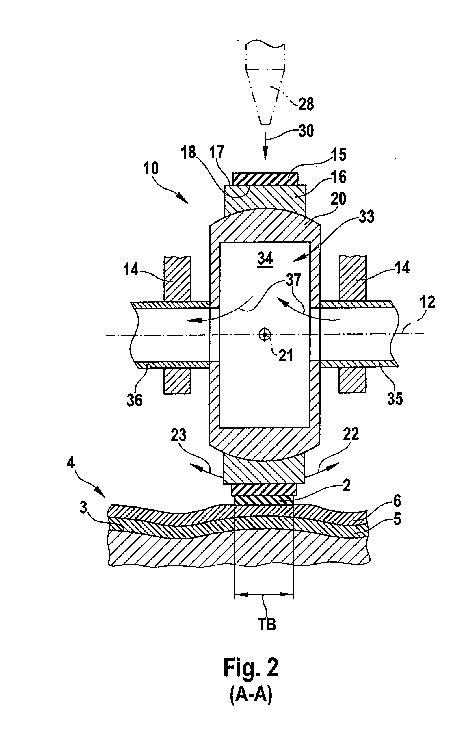
[0015] In the case of a further embodiment of the invention, the cooling device dissipates heat from the elastomer coating on the inside, the pressure roller being of a hollow form for a coolant to flow through it. The inside is intended in the present case to mean the side of the elastomer coating that is facing the circumference of the pressure roller. It is advantageous in the case of this arrangement that a closed cooling circuit can be used, it being possible for the cooling device to be formed very compactly and efficiently, because it is partially integrated in the pressure roller. Water or water mixed with alcohol come into consideration in particular as the coolant.

Problems solved by technology

However, these have virtually no elasticity, so that point contact between the pressure roller and the surface of the laminating device occurs in the case of highly contoured laminating devices.
The tapes to be laid are consequently not evenly pressed over the full width of the tape and poor consolidation or excessive pressing of the tape layers occurs.
Poor laminate quality, in particular with high porosities, and consequently poor component quality, are the consequence.
However, with this approach there is the disadvantage that the metallic pressure roller and the elastic coating have different coefficients of thermal expansion, which in the case of such shrunk-on coatings has the effect that they change their position on the pressure roller.
This then has the consequence after a short time that the coating is only partially in contact with the tape over the width of the latter, which in turn disadvantageously causes uneven pressing of the tape on the laminating device.

Method used


Image

  • Device for pressing a tape
  • Device for pressing a tape
  • Device for pressing a tape

Examples


Embodiment Construction

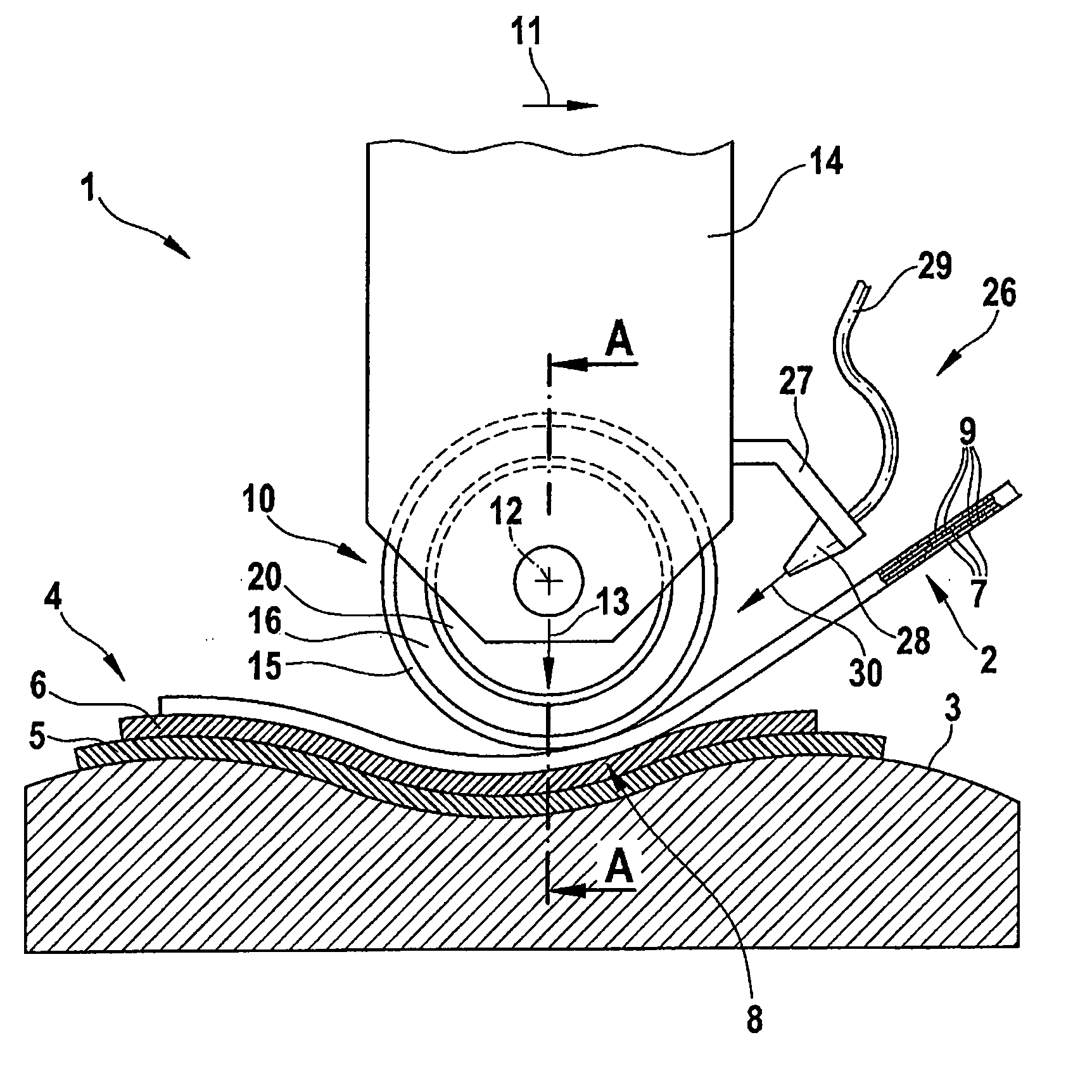
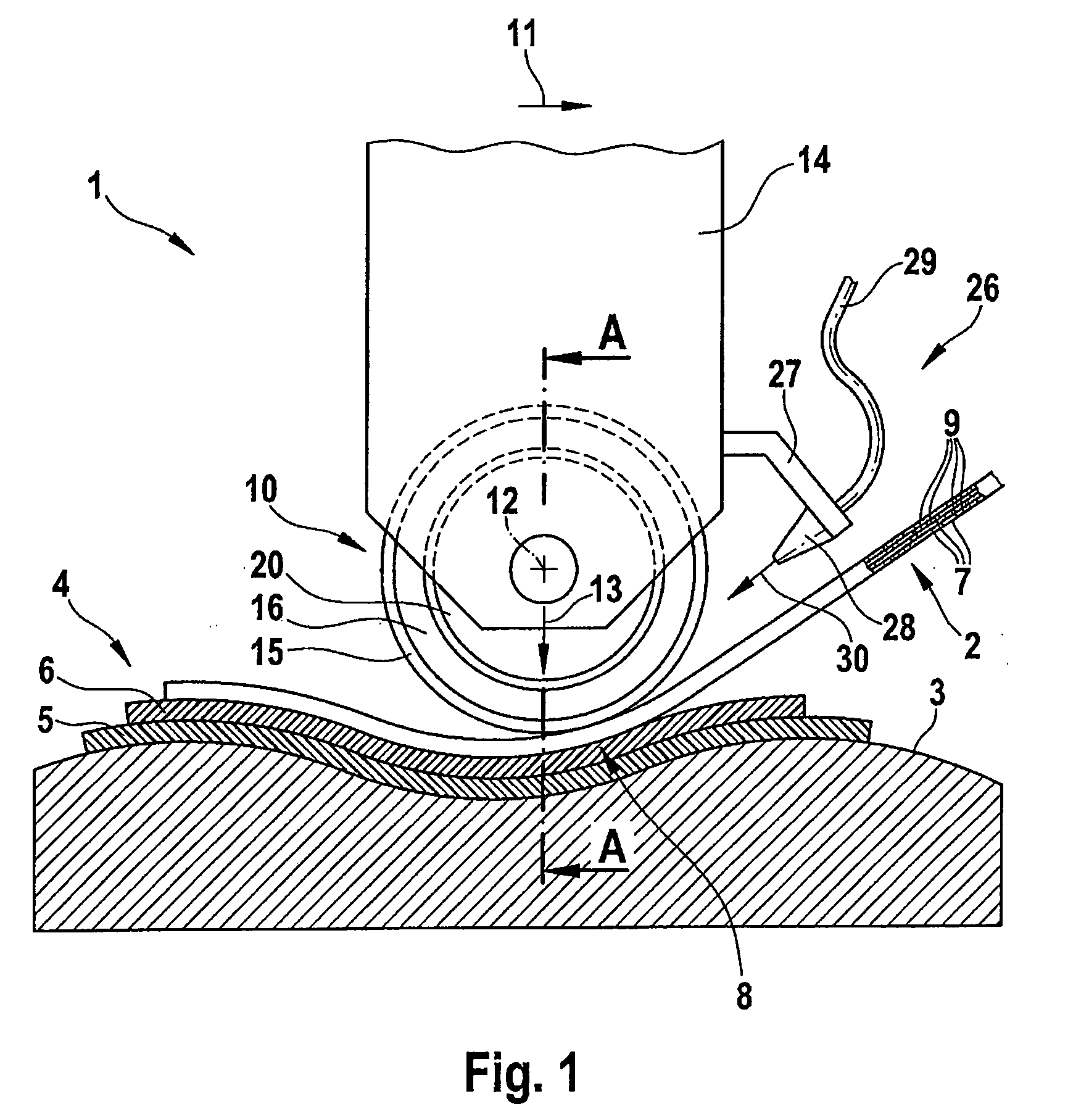
[0028]FIG. 1 shows in a side view a device 1 for the directed laying and pressing of tape 2 in strip form on a surface contour 3 of a laminating device 4. Laminate layers 5 and 6 have already built up on the surface contour 3.

[0029] The tape 2 has a structure of unidirectional carbon fibers 7 in the longitudinal direction of the tape, which are embedded in a thermoplastic matrix 9.

[0030] The tape 2 is first heated (not represented), the thermoplastic matrix 9 becoming at least partially melted. Subsequently, the hot tape 2 is fed to a pressure roller 10 of the device 1, which presses a portion 8 of the tape 2 onto the laminate layer 6, which in turn is supported by the laminate layer 5 and the surface contour 3. In this case, the pressure roller is moved in the direction of the arrow 11, it rotating about its axis of rotation 12 and being subjected to a force 13 in the direction of the arrow.

[0031]FIG. 2 shows a sectional view along the sectional line A-A from FIG. 1. The pressur...


PUM

PropertyMeasurementUnit
Temperatureaaaaaaaaaa
Electrical resistanceaaaaaaaaaa
Surfaceaaaaaaaaaa

Abstract

A device is disclosed for pressing a tape, in particular a thermoplastic, carbon-fiber reinforced tape, for a fiber / tow placement method. A portion of the tape can be pressed by means of a pressure roller on a variable surface contour of a laminating device. An elastomer coating for even pressing of the tape adheres to the circumference of the pressure roller with a material bond. This may provide the advantage that a permanent and reliable connection is created between the elastomer coating and the pressure roller, which furthermore can be easily produced.

Description

CROSS-REFERENCE TO RELATED APPLICATIONS [0001] This application claims the benefit of U.S. Provisional Application No. 60 / 854,020, filed Oct. 24, 2006 and German Patent Application No. 10 2006 058 584.4 filed Dec. 12, 2006, the entire disclosures of which are herein incorporated by reference.FIELD OF THE INVENTION [0002] The present invention relates to a device for pressing a tape. [0003] Although it can be applied to any devices, the present invention and the problems on which it is based are explained with reference to a device for a fiber / tow placement method for producing aircraft components. BACKGROUND OF THE INVENTION [0004] In the aircraft industry, efficient production methods for producing high-strength components from fiber reinforced plastics are becoming increasingly important. The fiber / tow placement method represents such a method. In this method, hot tape, in particular of high-strength thermoplastic materials in strip form with carbon fiber reinforcement, are laid a...

Claims


Application Information

Patent Timeline
IPC IPC(8): B32B37/02
CPCB29C70/386B32B2309/72B32B2309/02B32B37/0053
Inventor NAUMANN, NIKO
Owner AIRBUS OPERATIONS GMBH
Learn More