Capacitor-switched lossless snubber

a snubber and capacitor technology, applied in the direction of power electronics conversion, power conversion system, electrical apparatus, etc., can solve the problems of increasing the cost of the vehicle, reducing the efficiency of the vehicle, and the fuel economy of the vehicle, so as to achieve desirable converter efficiency, reduce the stress of the switch, and high switching frequency

Inactive Publication Date: 2008-04-24
BAUMAN JENNIFER +1
View PDF14 Cites 57 Cited by
  • Summary
  • Abstract
  • Description
  • Claims
  • Application Information

AI Technical Summary

Benefits of technology

[0014] In one aspect of the present invention, a boost converter in accordance with the present invention provides relatively high switching frequencies than prior art boost converters, with desirable converter efficiencies. The regenerative snubber of the present invention is relatively light in comparison with prior art hard-switched converters due to the smaller passive components required at a higher frequency. Other benefits of using the regenerative snubber circuit of the present invention include: lower switch stress at turn-off and turn-on, a lower duty cycle required for the equivalent voltage boost in the hard-switched converter, and the transfer of much of the switching losses to conduction losses in the auxiliary components, meaning switching frequency may generally be greatly increased before reaching the thermal limits of the IGBT. The regenerative snubber for boost converters of the present invention may not pose any practical limitations in terms of operating power or voltage boost. The regenerative snubber of the present invention has a relatively simple design and is relatively easily controlled. It provides relatively high efficiency and relatively desirable mass reduction. It is suited for a variety of applications such as fuel cell, hybrid-electric, and battery-electric vehicles, uninterruptible power supplies (UPS), and stationary generators requiring a voltage boost to connect to the grid such as fuel cells, photovoltaic arrays, and microturbines.

Problems solved by technology

However, conventional high-power boost converters are very large and heavy, partly due to the large inductors used in the design.
These heavy components negatively affect the fuel economy of the vehicles, add cost to the vehicle, and may add difficulty for packaging.
High specific power and high power density require high-frequency operation, which may lead to two potential problems for high-power (30 kW-100 kW) DC / DC converters.
Firstly, switching losses will increase proportionally with increasing frequency, which will reduce efficiency and increase cooling requirements.
Secondly, the power insulated gate bipolar transistors (“IGBTs”) commonly used in these converters are limited to hard-switching operation at 30 kHz or less [Powerex CM400DU-12NFH datasheet, www.pwrx.com], depending on power level.
However, resonant converters require careful matching of the operating frequency to the resonant tank components and operation failure can occur if there is any magnetic saturation or other unexpected drift in resonant frequency.
Furthermore, it is difficult to design filters and control circuits because of the wide range of switching frequencies.
The auxiliary circuits can be very complicated and require numerous extra components, usually including extra magnetic components.
Finally, passive methods can cause higher component stresses and have generally been shown to provide only marginal reductions in switching losses.
Some disadvantages of active methods are in complexity of control or limitations in terms of voltage-boost range and load range.
Finally, some active methods have hard-switching of the auxiliary switch(es) and many have a high component count, including heavy and expensive inductors.

Method used


Image

  • Capacitor-switched lossless snubber
  • Capacitor-switched lossless snubber
  • Capacitor-switched lossless snubber

Examples


Embodiment Construction

Circuit Design

[0035] An analysis is performed on a high-power hard-switched boost converter in order to compare the turn-on and turn-off losses of the switch. A boost converter with specifications similar to what is used in fuel cell or electric vehicles (200V input, 400V output, 60 kW) was simulated in PSPICE. The part number for the IGBT model used is CM400HA-12E. In order to obtain practical results, the gate resistance is chosen to limit the maximum gate current to 10% of the rated current of the switch. The simulation results show that the energy loss at turn-on is approximately 2 mJ, whereas the energy loss at turn-off is approximately 21 mJ.

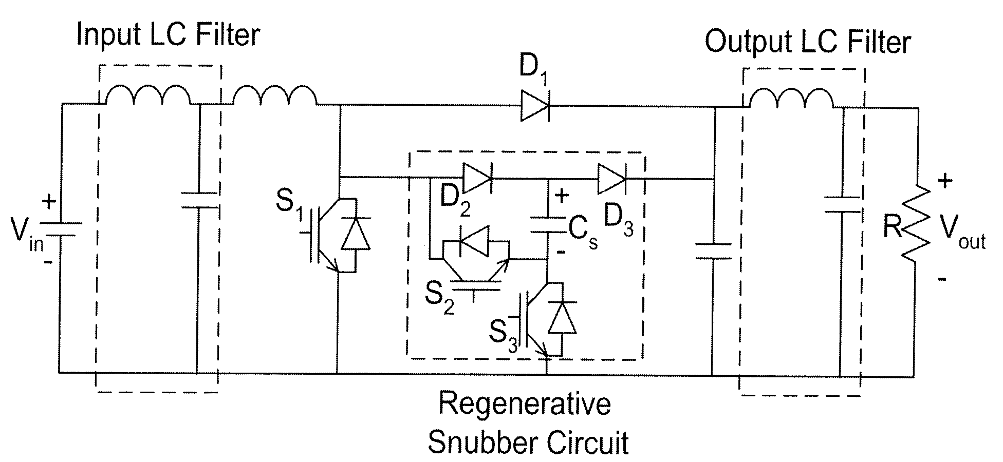
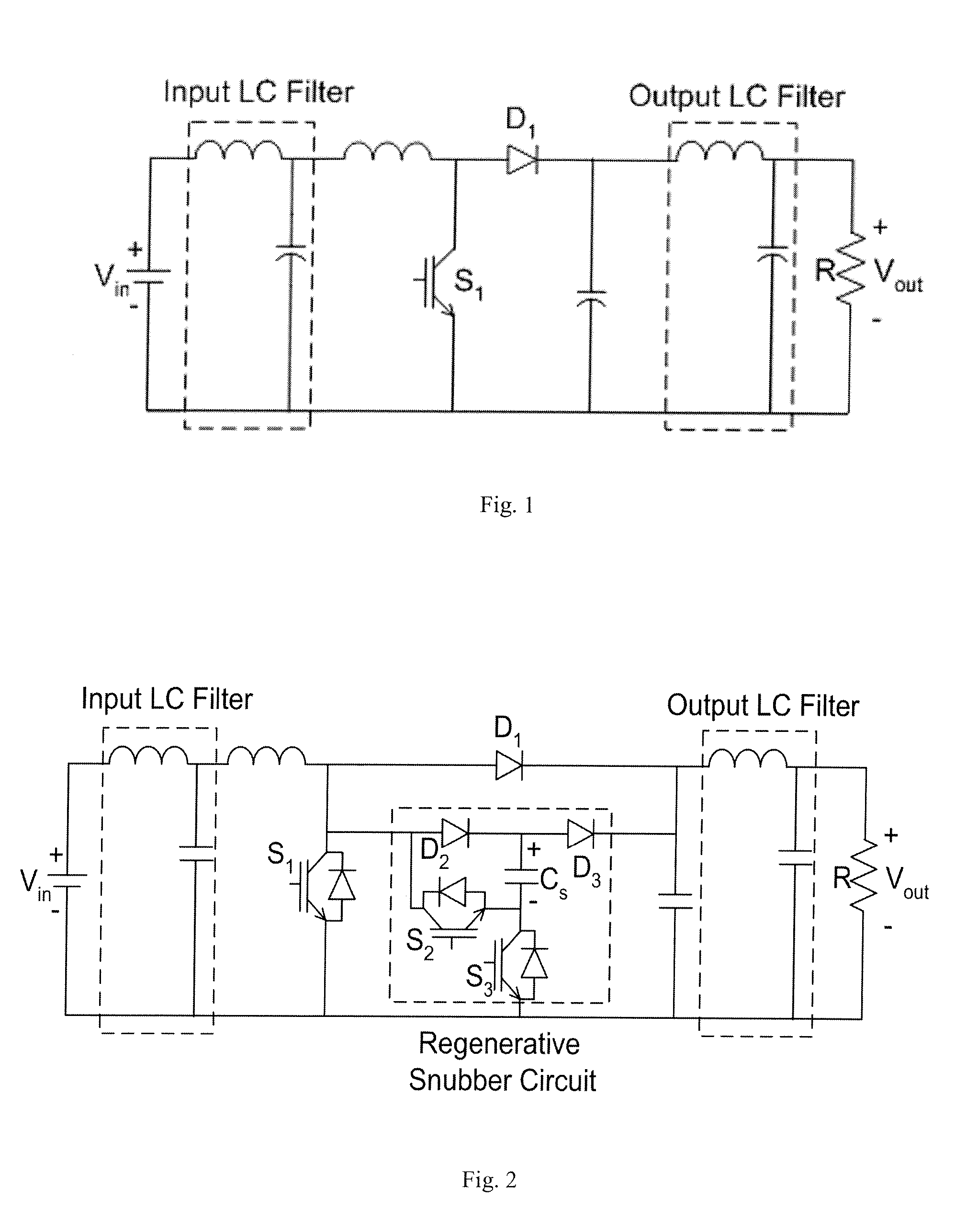
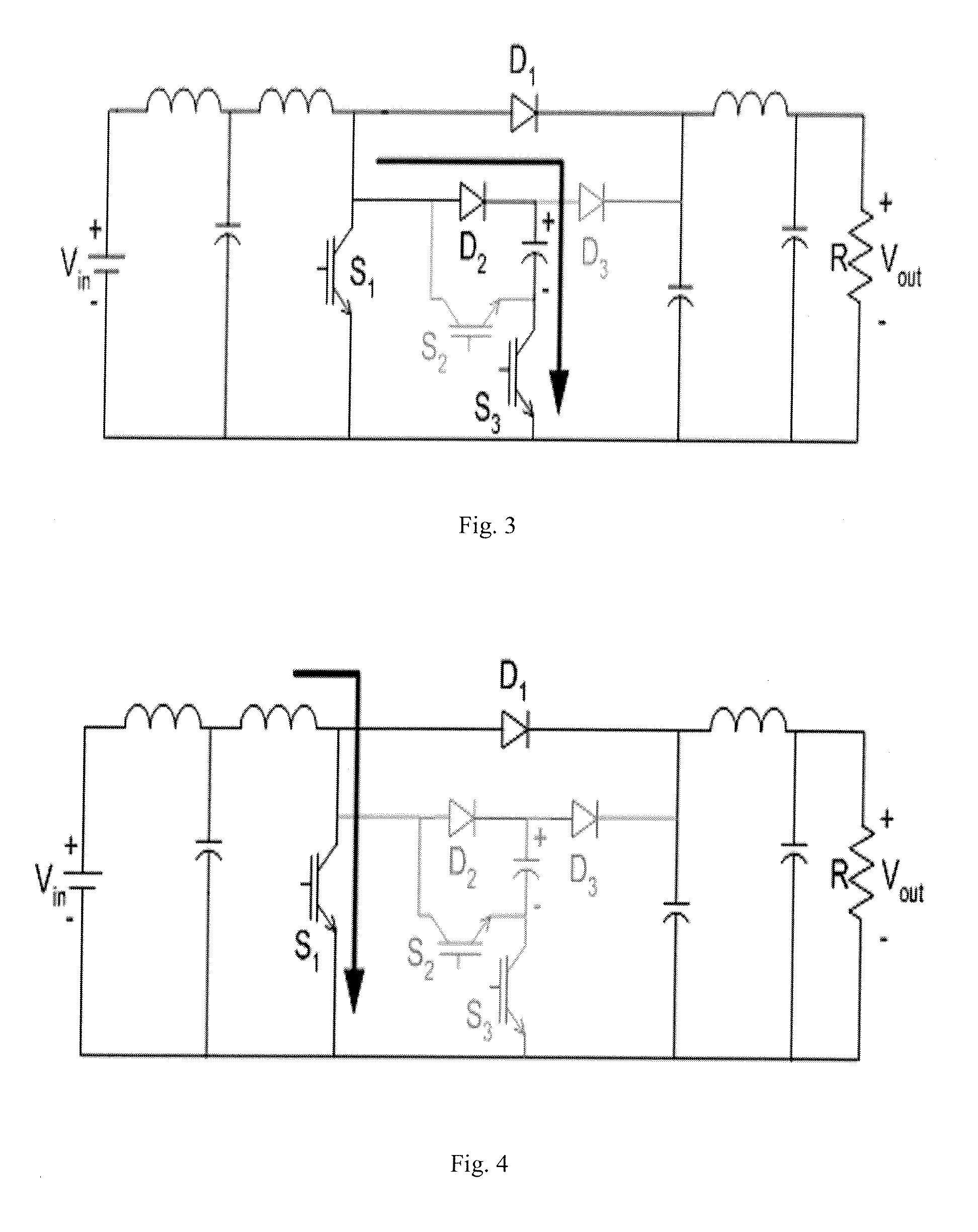
[0036] The much higher value of turn-off losses in an IGBT can be explained by the fact that there is a significant current tail as the voltage across the switch rises rapidly during turn-off. Hence, the capacitor-switched regenerative snubber circuit described herein focuses on reducing the turn-off losses of the IGBT. However, the des...


PUM


Abstract

A regenerative snubber circuit for a boost converter is provided which greatly reduces the switching losses of the IGBT in the converter. The circuit uses no additional magnetic components, has a simple control strategy, is relatively low-cost, and provides an increase in efficiency and decrease in size and mass of the converter.

Description

[0001] This application claims priority from U.S. Provisional Patent Application No. 60 / 818,537, filed Jul. 6, 2006.TECHNICAL FIELD [0002] The present invention relates to DC / DC power converters. In particular, the present invention relates to a regenerative snubber for a boost converter. BACKGROUND OF THE INVENTION [0003] High power DC / DC converters are a crucial component of emerging vehicle technologies, including hybrid-electric, battery-electric, and fuel cell vehicles, to interconnect and manage their power systems. Typically, a voltage boost effected by a boost converter is required to step-up the lower voltage provided by a fuel cell or battery to the higher voltage required by the vehicle's electric motor. However, conventional high-power boost converters are very large and heavy, partly due to the large inductors used in the design. These heavy components negatively affect the fuel economy of the vehicles, add cost to the vehicle, and may add difficulty for packaging. [000...

Claims


Application Information

Patent Timeline
Patent Type & Authority Applications(United States)
IPC IPC(8): H02H7/10
CPCH02M1/34Y02B70/1491H02M2001/342Y02B70/10H02M1/342
Inventor BAUMAN, JENNIFERKAZERANI, MEHRDAD
Owner BAUMAN JENNIFER
Why Eureka
Try Eureka