Self-sealing well cement composition

a well cement and composition technology, applied in the direction of sealing/packing, wellbore/well accessories, chemistry apparatus and processes, etc., can solve the problems of reducing the production of wells, high temperature, high pressure, failure and collapse of cement, etc., to minimize or mitigate the unwanted migration of water or hydrocarbons

Active Publication Date: 2008-05-01
BAKER HUGHES INC
View PDF10 Cites 71 Cited by
  • Summary
  • Abstract
  • Description
  • Claims
  • Application Information

AI Technical Summary

Benefits of technology

[0024] What is disclosed is a composition and method of producing a self-sealin...

Problems solved by technology

The downhole conditions of wells pose extreme conditions for the cement, exposing it to high temperatures, high pressures, and variable tectonic forces.
These conditions frequently lead to the formation of fractures in the concrete, and ultimately failure and collapse of the cement.
This damage decreases the production of the well, and may require treatment of the well to repair or replace the cement.
Cement operations performed in wellbores under high stress conditions may present particular problems, among other things, difficulty in obtaining good wellbore isolation and/or maintaining mechanical integrity of the wellbore over the life of the well.
The induced stress causes fractures within the cement sheath which lead to fluid intrusion into the wellbore, including intrusion of water, gas, or other fluids.
Once established, maintaining this zonal isolation is typically impacted by the particular stress environment found while the well is being completed and produced.
Further, if the well is completed using a complex completion such as a multi-lateral system, the cement sheath may be subject to shattering and subsequent loss of bond due to pipe impact.
Conventional well cement compositions are typically brittle when cured.
These conventional cement compositions often fail due to stresses, such as radial and/or tangential stresses, that are exerted on the set cement.
In other cases, cements placed in wellbores may be subjected to mechanical stress induced by vibrations and impacts resulting from operations, for example, in which wireline and pipe conveyed assembly are moved within the wellbore.
Conventional wellbore cements typically react to excessive stress by failing.
“Cement failure” refers to cracking, shattering, debonding from attached surfaces (such as exterior surfaces of a pipe string and/or the wellbore face), or otherwise losing its original properties of strength and/or cohesion.
Stress-induced cement failure typically results in loss of formation isolation and/or loss of wellbore mechanical integrity, such as casing collapse or shearing of the casing.
This in turn may result in loss of production, loss of the wellbore, pollution, and/or hazardous conditions.
For example, completions having relatively thin annular cement sheaths between pipe strings and/or between the outside surface of a pipe string and the inside formation wall may be particularly susceptible to stress-induced cement damage.
Such lateral or multi-lateral completions may be particularly susceptible to stress induced cement failures for a number of reasons.
For example, the juncture between the primary and secondary lateral wellbores is typically exposed to mechanical stresses induced by a large number of subsequent operations involving the running of tools through the junction point.
When conventional cements are employed in lateral or multi-lateral wellbore completions, the set conventional cement is typically too brittle ...

Method used


Image

  • Self-sealing well cement composition
  • Self-sealing well cement composition

Examples


example 1

Preparation of Fractured Cement Samples

[0041] Joppa H cement is commercially available from Lafarge's Joppa Illinois plant. Cements are commonly referred to by an API specification class. The class is assigned based upon, among other characteristics, the percentage of water in the cement. Class A has 46%, B has 46%, C has 56%, G has 44%, and H has 38%. In the examples presented herein, Joppa Class H cement is used. Cement samples were prepared in accordance with API Recommended Practice 10B, 22nd edition, December 1997.

[0042] LANXESS BAYMOD® N VP KA 8641 was added to Joppa Class H cement so that the percentage of additive was 15% (i.e. 15 pounds additive per 94 pounds of cement). The samples were cured at 140° F. and 3000 psi in core molds (1″ diameter×2″ length) for 72 hours. The samples were released from the molds and fractured prior to testing. Fracturing was accomplished by a chisel impact along a scored edge. The fractured molds were re-connected and wrapped with Teflon and ...

example 2

Permeability Testing of Fractured Samples

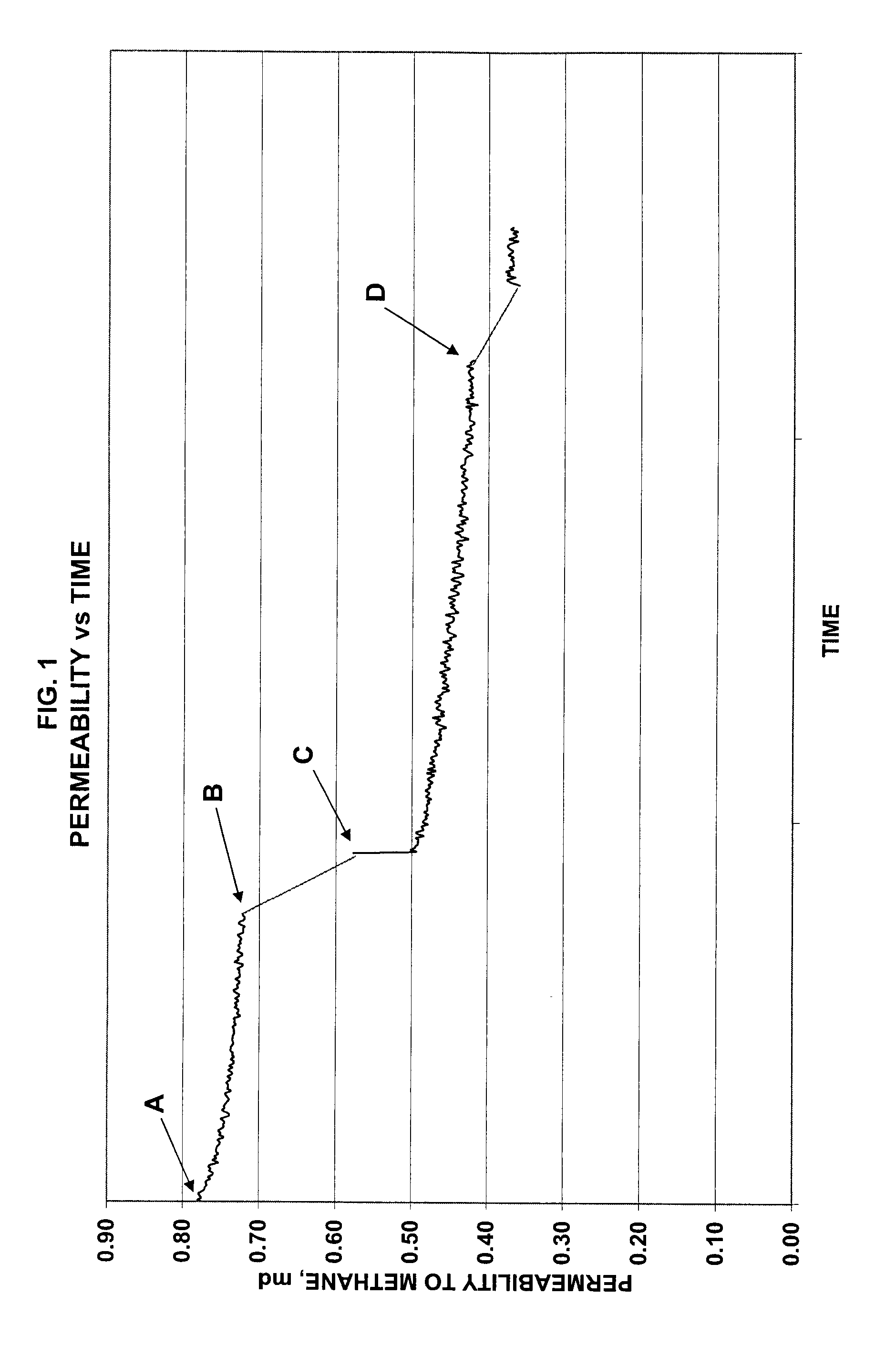
[0044] Testing was performed on the mechanically fractured cement samples. Flow testing was performed at ambient temperature with commercial grade methane gas (93% methane). Confining stress and injection pressure were varied to keep the effluent gas rate at less than 60 cm3 / min. Differential pressure was monitored over time.

[0045] Permeability is a measure of the ability of a material, in this case the fractured cement samples) to transmit a fluid. With the differential pressure measured for the cement sample tests, permeability was calculated using Darcy's Law. Darcy's law is a simple proportional relationship between the instantaneous discharge rate through a porous medium, the viscosity of the fluid, and the pressure drop over a given distance: Q=-κ⁢ ⁢Aμ⁢(Pb-Pa)L

where Q=the total discharge (units of volume per time, e.g., cm3 / min); κ=the permeability of the fractured cement sample (measured in mD or milliDarcy); A=the cross-sectional ...


PUM

PropertyMeasurementUnit
Percent by massaaaaaaaaaa

Abstract

A cement composition is provided including a cement and a low reactivity particle coated with a swellable polymeric material. The low reactivity particle is coated with a swellable polymeric material at a concentration of about 10 weight percent to about 50 weight percent, based on the weight of the cement. The swellable polymeric material swells to a larger volume when exposed to one or more hydrocarbons, depending on the selected polymeric material. The cement composition is used in a method as a self-sealing cement for cementing an oil and gas well, thereby minimizing or mitigating the unwanted migration of water or hydrocarbons.

Description

CROSS REFERENCE TO RELATED APPLICATIONS [0001] The present application is a continuation-in-part application of U.S. patent application Ser. No. 11 / 598,382, which is a divisional application to U.S. patent application Ser. No. 10 / 605,946, now U.S. Pat. No. 7,156,173, which claims priority to U.S. Provisional Patent Application Ser. No. 60 / 424,751 filed Nov. 8, 2002, the contents of each are incorporated by reference herein in their entireties. BACKGROUND OF THE INVENTION [0002] The present invention relates generally to novel cement compositions and, more specifically, to cement compositions that are suitable for the high temperature, high pressure conditions commonly found in oil and gas wells. In particular, highly resilient cement compositions having improved sealing properties are disclosed. [0003] Cement is commonly used to seal the wellbore of oil and gas wells. The downhole conditions of wells pose extreme conditions for the cement, exposing it to high temperatures, high pres...

Claims


Application Information

Patent Timeline
IPC IPC(8): E21B33/13
CPCC04B20/1022C04B20/1037C04B20/1051C04B28/02C04B2103/0028C04B2103/0049C09K8/467C04B14/022C04B14/041C04B14/047C04B14/06C04B20/008C04B20/0024
Inventor MUELLER, DAN THOMASBRANNON, HAROLD DEANBRAY, WINDALL SCOTT
Owner BAKER HUGHES INC
Why Eureka
Try Eureka