Apparatus and Methods for Active Mold Decompression & Melt Accumulation in a Shooting Pot Reservoir of an Injection Molding Machine

Inactive Publication Date: 2008-05-15
HUSKY INJECTION MOLDING SYST LTD
View PDF2 Cites 3 Cited by
  • Summary
  • Abstract
  • Description
  • Claims
  • Application Information

AI Technical Summary

Benefits of technology

[0025]In another aspect of the present invention there is provided a method of developing volume in a shooting pot reservoir in an injection cylinder containing a moveable plunger and an injection piston, the method comprising: initially connecting together and pulling back the plunger and the injection piston to define a first volume within the shooting pot reservoir; disconnecting the plunger from the injection piston and pulling back the injection piston to a predefined check point; and accumulating melt in the first volume and permitting the plunger to be pushed back by action of the melt, the volume of the shooting pot reservoir thereby increasing as the plunger moves towards the injection piston at the predefined check point.
[0030]Advantageously, the present invention provides a simplified de-compression system that reduces the likelihood of drool from a cavity or runner systems while furthermore reducing shear stresses experienced within a melt during accumulation in a shooting pot. The system is operator friendly in that it is easy to set up and requires only knowledge of the final shot size / volume to be injected and hence the end point of travel of the injection piston. Use of a simple position switch or timing calculation may act as a trigger for coupling and decoupling. Beneficially, the present invention does not require detailed signal processing, nor multiple measurements of pressure or plunger location.

Problems solved by technology

Processing of molten magnesium is somewhat abrasive on the 
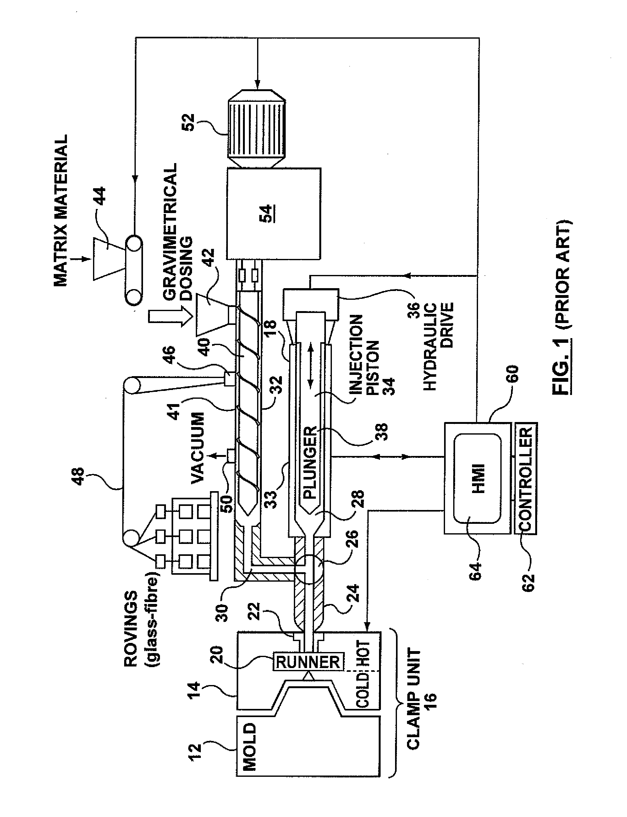
system components, especially the extruder unit, and it is also necessary for the mold to be treated with release agents to facilitate part de-molding; these are two obvious drawbacks.ii) Water-Injection Technology (WIT) that operates to produce hollow plastic components.
Depending on part shape, this technology can unfortunately produce non-uniform wall thicknesses in the finished article, since the flow and action of pressurized water cannot be deterministically controlled.
Some of the physical bulk of the molded part is thus removed, but this also potentially reduces the inherent physical strength of the molded part.iii) Gas-assisted injection technology employs a similar concept to WIT, albeit that the phase of the evacuating component is different.iv) In-line compounding (particularly in the sense of two-stage injection units).
Additionally, the abrasive nature of these fibres causes barrel wear issues which must be addressed either through regular maintenance of the machine or the provisioning of appropriate barrel liners and / or screw geometries.
Consequently, the TSE generally operates in a discontinuous mode (where plasticizing operation is periodically restricted) since the TSE is periodically isolated from any form of collection vessel and continuous plasticization would present logistical storage problems for the system, since the screws in a TSE do not reciprocate to create a reservoir downstream of them in the barrel.
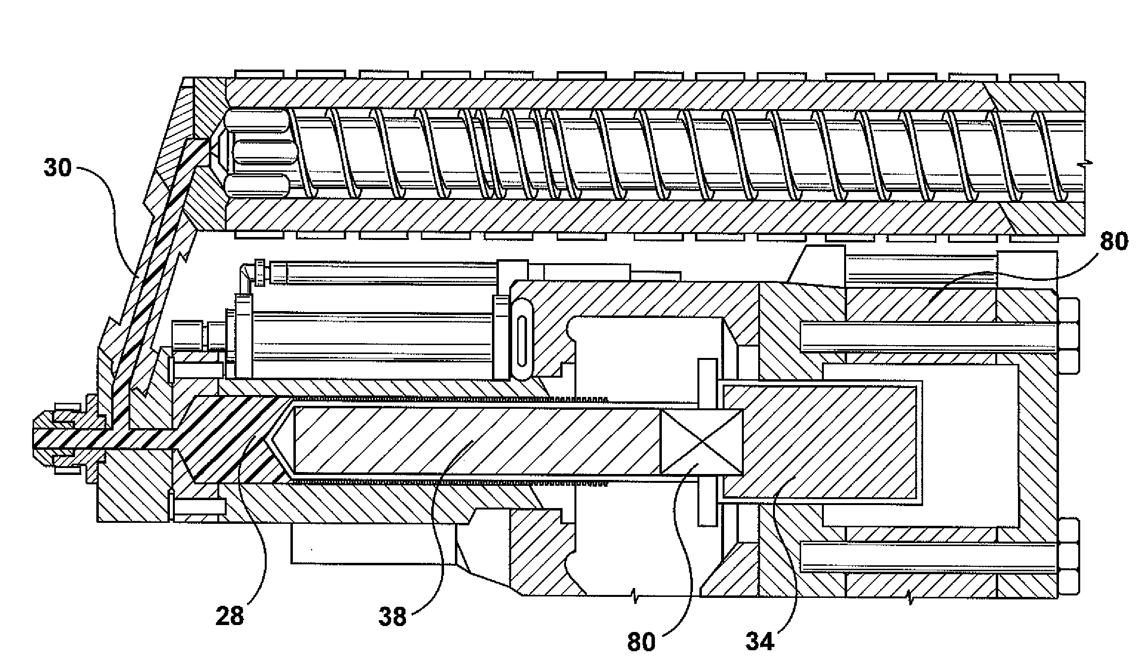
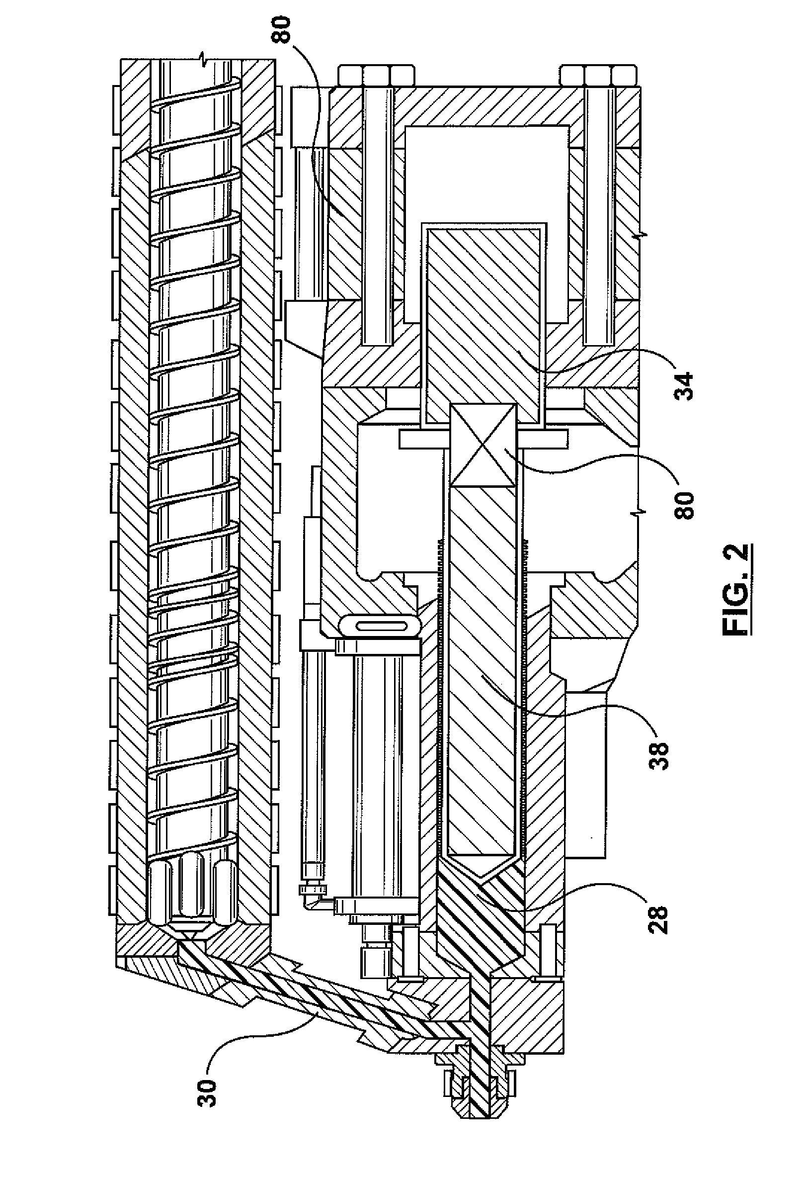
In any two-stage system, one of the problems that must be addressed relates to possible drooling of melt at the non-accessible / non-visible interface between the hot and cold regions of the mold.
Unfortunately, drooling can result in solidification of the plastic and this can cause both future contamination of an injection shot and / or a complete blockage or a flow restriction within the melt path from the shooting pot to the mold.
In relation to any form of flow restriction (whether complete or partial), the system is therefore susceptible to different fill profiles between successful cycles; this is unacceptable.
Any change in the flow fill profile can also result in undesirable weld lines occurring at uncontrollable positions within the molded part.
These weld lines are reflective of areas on non-homogeneity and, consequently, cause the molded part to experience different, uncontrolled and undesirable mechanical properties at different locations within its structure.
This slow, backwards movement may have a limited decompression effect on the hot runner.
[As will be understood, shear effects have the results of both reducing fibre length (in-line compounding applications) and affecting general melt properties / quality].
Unfortunately, while valve gating can provide an effective shut off (anti-drool) capability, valve gate technology cannot be applied to an in-line compounding environment where long fibres can potentially become entwined or otherwise wrapped around the valve stem, whereafter operation of the valve stem is restricted or stopped.
Consequently, the signal processing and control is relatively complex and expensive and the melt always experiences some pressure as it abuts against and pushes the plunger (notwithstanding that the plunger's movement is assisted).
In any event, the location of the transducer in the transfer channel is not ideal and its pressure measurement therefore relates to the extrusion pressure and not the pressure in the shooting pot reservoir.
Location of the pressure transducer in the barrel is possible, but not considered particularly viable.

Method used


Image

  • Apparatus and Methods for Active Mold Decompression & Melt Accumulation in a Shooting Pot Reservoir of an Injection Molding Machine
  • Apparatus and Methods for Active Mold Decompression & Melt Accumulation in a Shooting Pot Reservoir of an Injection Molding Machine
  • Apparatus and Methods for Active Mold Decompression & Melt Accumulation in a Shooting Pot Reservoir of an Injection Molding Machine

Examples


Embodiment Construction

[0038]FIG. 1 shows a typical injection molding machine 10 (although in this case an in-line compounding machine) that can be adapted to support an active decompression function according to the various embodiments of the present invention. Although represented as a two-platen system, the machine could equally be a three platen machine (for example).

[0039]Like conventional machines, during each injection cycle, the molding machine 10 produces a number of plastic parts corresponding to a mold cavity or cavities defined by complementary mold halves 12, 14 located within the machine 10.

[0040]The injection-molding machine 10 includes, without specific limitation, a clamp unit 16 as well as an injection unit 18 for plasticizing and injecting material. In operation, the movable platen is moved relative to the fixed platen by means of stroke cylinders or the like. Clamp force is developed in the machine, as will readily be appreciated, through the use of tie bars and a tie-bar clamping mech...


PUM

PropertyMeasurementUnit
Timeaaaaaaaaaa
Pressureaaaaaaaaaa
Sizeaaaaaaaaaa

Abstract

Active decompression to prevent melt drool from a mold (12, 14) or runner system (20) is achieved through the selective coupling and de-coupling of an injection piston (34) to a plunger (38). Following successive injection (FIG. 5a) and hold phases (FIG. 5b) of an injection molding process (FIG. 5), the runner and channel system is partially de-compressed (FIG. 5c) by drawing back together, over a short distance, the plunger (38) and the injection pressure (34) as one unit. The injection piston is then mechanically de-coupled from the plunger (FIG. 5e), with the injection piston (34) withdrawn to essentially its final shot position, but minus a customary packing distance (6). Plastic melt (100), extruded into a shooting pot (28) positioned in front of the plunger (38), is permitted to push the plunger backwards, but now with minimal work expenditure. When the plunger again contacts (FIG. 5f) the injection piston (34), melt pressure now causes both units to be moved back to reach a final shot size volume. Finally, the injection piston (34) drives the plunger (38) forward to eject melt accumulated within the shooting pot (28).

Description

FIELD OF THE INVENTION[0001]This invention relates, in general, to the operation and configuration of a two-stage injection molding machine and is particularly, but not exclusively, applicable to a melt accumulation stage (involving collaboration between an injection piston and plunger in an injection cylinder) of an in-line compounding machine that operates to produce a shot of plastic melt containing glass fibre (or similar) additives.SUMMARY OF THE PRIOR ART[0002]Injection molding technology supports the production of molded parts of varying sizes, e.g. bottle preforms, car bumpers and component housings. The benefits of injection molding technology include cycle speed, consistently reproducible part quality and cost. Especially in the context of plastic injection molding, parts are relatively light when compared with cast steel or machined metal alternatives.[0003]In relation to large-sized, lightweight molded parts or parts that require high residual strength, injection molding...

Claims


Application Information

Patent Timeline
IPC IPC(8): B29C45/80
CPCB29C45/531B29C2045/466B29C45/54
Inventor UJMA, ANDREASJUARISTI-TELLO, ENRIQUE
Owner HUSKY INJECTION MOLDING SYST LTD
Why Eureka
Try Eureka