Control system for rotary electric machine with salient structure

a control system and rotary electric machine technology, applied in the direction of motor/generator/converter stopper, dynamo-electric gear control, dynamo-electric converter control, etc., can solve the problem that the control system disclosed is difficult to properly obtain and the publication of the control system may be more difficult to properly calculate the rotation angle of the rotor

Active Publication Date: 2008-05-15
DENSO CORP
View PDF12 Cites 44 Cited by
  • Summary
  • Abstract
  • Description
  • Claims
  • Application Information

AI Technical Summary

Benefits of technology

[0011]According to one aspect of the present invention, there is provided a system for controlling rotation of a rotor of a multiphase rotary electric machine in relation to a stator thereof. An output of the multiphase rotary electric machine is controlled based on an input signal thereto. The system includes a superimposing unit that superimposes a first frequency signal on the input signal to the multiphase rotary electric machine. The first frequency signal has a first phase and a first period, and the first period is different from a period of rotation of the rotor. The system includes an amplitude detector that detects an amplitude of a second frequency signal. The second frequency signal is actually propagated in the multiphase rotary electric machine with a second phase based on the superimposed first frequency signal. The system includes a rotation angle determiner that determines a rotation angle of the rotor so as to eliminate a difference between the detected amplitude of the second frequency signal and a predetermined target amplitude thereof.
[0012]According to another aspect of the present invention, there is provided a system for controlling rotation of a salient rotor of a multiphase rotary electric machine in relation to a stator thereof. An output of the multiphase rotary electric machine is controlled based on an input signal thereto. The system includes a superimposing unit configured to superimpose, on the input signal to the multiphase rotary electric machine, a direct-axis frequency signal directed in a direct axis of the rotor and a quadrature-axis frequency signal directed in a quadrature axis of the rotor orthogonal to the direct axis. Each of the direct-axis and quadrature-axis frequency signals has a first phase and a first period. The first period is different from a period of rotation of the rotor. The system includes a tentative angle calculator configured to calculate a tentative rotation angle of the rotor based on a second phase of a first frequency signal. The first frequency signal is actually propagated in the multiphase rotary electric machine with the second phase based on the superimposed direct axis frequency signal. The system includes a corrector configured to correct the tentative rotation angle calculated by the tentative angle calculator so as to eliminate a difference between an amplitude of a second frequency signal and a predetermined target amplitude thereof. The second frequency signal is actually propagated in the multiphase rotary electric machine with the second phase based on at least the superimposed quadrature-axis frequency signal.

Problems solved by technology

This may make it difficult for the control system disclosed in the US Patent Publication to properly calculate the rotation angle of the rotor.
For this reason, the control system disclosed in the US Patent Publication may be more difficult to properly obtain the rotation angle of the rotor due to the magnetic saturation.

Method used


Image

  • Control system for rotary electric machine with salient structure
  • Control system for rotary electric machine with salient structure
  • Control system for rotary electric machine with salient structure

Examples


first embodiment

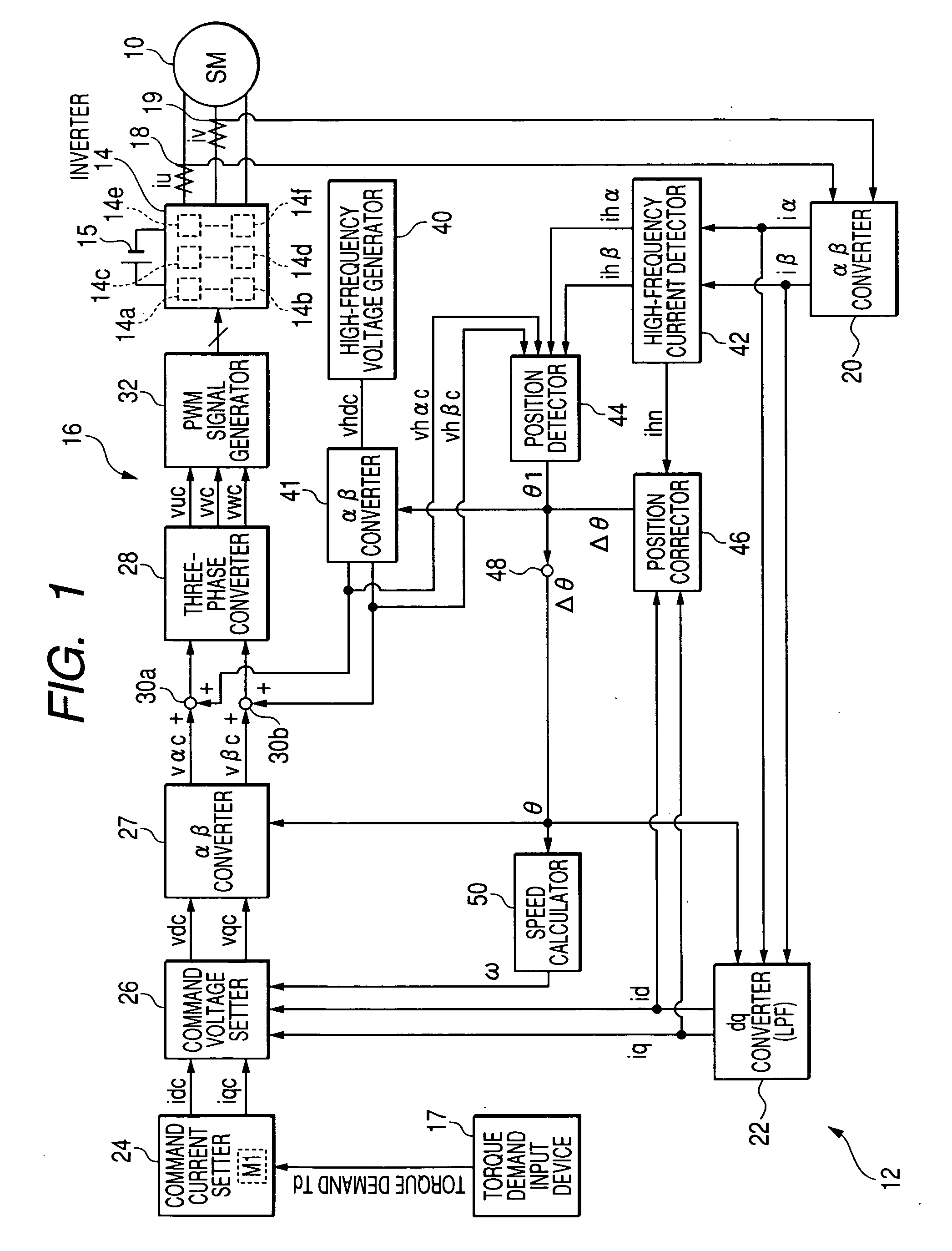
[0065]Referring to the drawings, in which like reference characters refer to like parts in several figures, particularly to FIG. 1 there is illustrated the three-phase motor 10 and a control system 12 for controlling the motor 10 according to a first embodiment of the present invention. In the first embodiment, the three-phase motor 10 is an IPMSM (Interior Permanent Magnet Synchronous Motor).

[0066]Specifically, the three-phase motor, referred to simply as “motor”10 is provided with a rotor 10a whose cylindrical iron rotor core 10a1 is fixedly fitted around the outer periphery of a crankshaft of an engine installed in the hybrid vehicle.

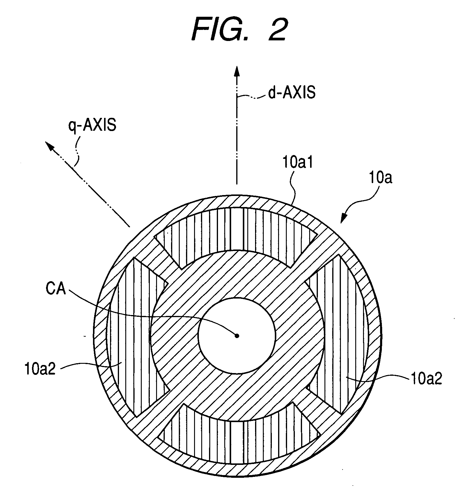
[0067]The rotor 10a has a salient structure.

[0068]Specifically, as illustrated in FIG. 2, the rotor 10a is provided at circumferential portions of the rotor core 10a1 with a number of such as four, permanent magnet 10a2 each having a substantially arc-shape in its lateral cross section.

[0069]The four permanent magnets 10a2 are so embedded in the oute...

second embodiment

[0210]FIG. 11 schematically illustrates an example of the structure of a control system 12A according to a second embodiment of the present invention. Different structural and functional points of the control system 12A from the control system 12 according to the first embodiment will be mainly described hereinafter. Like parts between the control systems 12 and 12A, to which like reference characters are assigned, are omitted or simplified in description.

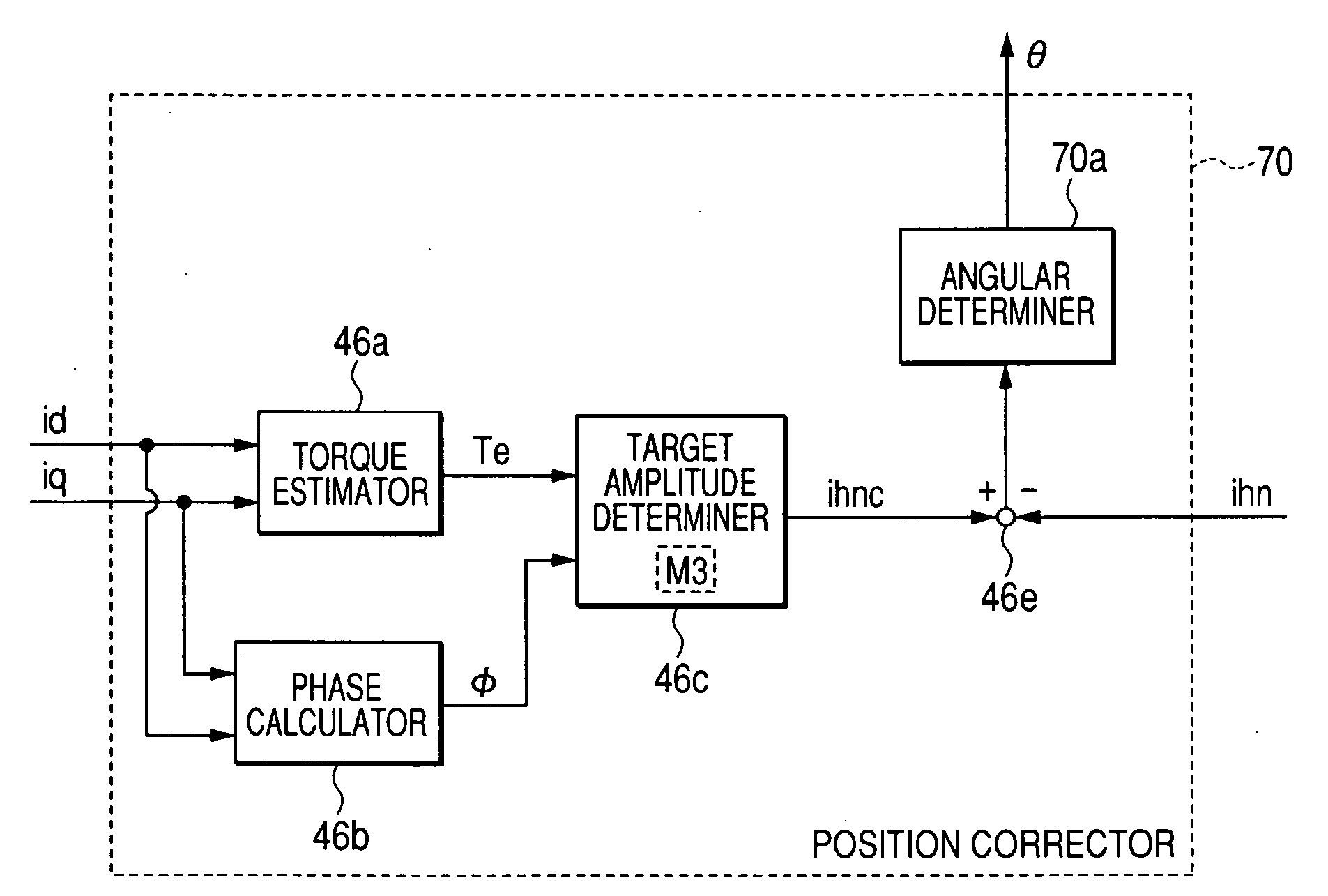
[0211]As illustrated in FIG. 11, a controller 16A of the control system 12A includes a dq converter 22a, the command-current setter 24, fourth and fifth adders 25a and 25b, the command-voltage setter 26, the αβ converter 27, the three-phase converter 28, and the PWM signal generator 32. The controller 16A also includes a high-frequency current generator 60, an αβ converter 41a, a dq converter 41b, a high-frequency voltage detector 66, a position detector 68, a position corrector 70, the third adder 48, and the speed calculator 50.

[...

third embodiment

[0240]A control system according to a third embodiment of the present invention will be described hereinafter. Like parts between the control system 12 according to the first embodiment and the control system according to the third embodiment, to which like reference characters are assigned, are omitted or simplified in description.

[0241]In the control system according to the third embodiment, as illustrated in FIG. 13, the target amplitude determiner 46c works to determine the amplitude of the actually propagated high-frequency signal (the α- and β-axis current components ihα and ihβ) associated with the estimated output torque Te, the calculated phase φ of the drive current vector, and the rotation speed ω of the motor 10 (see step S14 of FIG. 9). Specifically, the amplitude of the actually propagated high frequency signal (α- and β-axis current components ihα and ihβ) is changed with change in the RPM of the motor 10.

[0242]The control system according to the third embodiment, in ...


PUM


Abstract

In a system for controlling rotation of a rotor of a multiphase rotary electric machine in relation to a stator thereof, a superimposing unit superimposes a first frequency signal on the input signal to the multiphase rotary electric machine. The first frequency signal has a first phase and a first period, and the first period is different from a period of rotation of the rotor. An amplitude detector detects an amplitude of a second frequency signal. The second frequency signal is actually propagated in the multiphase rotary electric machine with a second phase based on the superimposed first frequency signal. A rotation angle determiner determines a rotation angle of the rotor so as to eliminate a difference between the detected amplitude of the second frequency signal and a predetermined target amplitude thereof.

Description

CROSS REFERENCE TO RELATED APPLICATIONS[0001]This application is based on Japanese Patent Applications 2006-306912 and 20077056008 filed on Nov. 13, 2006 and Mar. 6, 2007, respectively. This application clams the benefit of priority from the Japanese Patent Applications, so that the descriptions of which are all incorporated herein by reference.FIELD OF THE INVENTION[0002]The present invention relates to systems for estimating a rotation angle of a rotor of a rotary electric machine with respect to a fixed reference axis of a stator thereof according to change in a periodic signal created in the rotary electric machine.BACKGROUND OF THE INVENTION[0003]An example of various types of control systems for a three-phase motor is disclosed in U.S. Pat. No. 6,555,988 B2 corresponding to Japanese Patent Application Publication No. 2001-1169590.[0004]A control system disclosed in the US Patent Publication superimposes a high-frequency AC voltage on an output signal from an inverter in an est...

Claims


Application Information

Patent Timeline
Patent Type & Authority Applications(United States)
IPC IPC(8): H02P21/14H02P6/08
CPCH02P21/14
Inventor INOKUMA, KENJI
Owner DENSO CORP
Why Eureka
Try Eureka