Beam shifting element for an optical storage system

a technology of optical storage system and beam shifting element, which is applied in the field of beam shifting element, can solve the problems of shifting pixels, strong distortion of hologram, and similar problems for other types of optical storage media, and achieve the effect of reducing the distortion of light beams and simplifying the fabrication of beam shifting elements

Inactive Publication Date: 2008-05-15
THOMSON LICENSING SA
View PDF13 Cites 2 Cited by
  • Summary
  • Abstract
  • Description
  • Claims
  • Application Information

AI Technical Summary

Benefits of technology

[0012]Advantageously, the second optical element and the third optical element form a unit. This simplifies the fabrication of the beam shifting element, as the adjustment of one optical element can be omitted. In addition, the movement of the second optical element and the third optical element is automatically synchronized.
[0013]Preferably, an apparatus for reading from and / or writing to optical storage media, e.g. holographic storage media, has a beam shifting element according to the invention for shifting a light beam in a first direction. The beam shifting element is useful for keeping the light beam on the optical axis of an objective lens, which is moved for tracking or for keeping it on a fixed position relative to a rotating disk surface during recording. In this way distortions of the light beam are minimized. In case the light beam also needs to be shifted in a second direction, a further beam shifting element according to the invention is preferentially provided. Of course, the beam shifting element according to the invention can likewise be used in any other optical setup where a shift of a light beam is needed.
[0014]Advantageously, the apparatus has a control element for adjusting the shift of the light beam caused by the beam shifting element. The control element adjusts the shift of the light beam in response to a position signal, which indicates a deflection of the light beam from the desired position. Alternatively, the control element adjusts the shift of the light beam in response to a signal derived from the control signal of an actuator of the objective lens. In this way it is ensured that the light beam automatically remains on the optical axis of the objective lens. The control signal of the actuator may be low-pass filtered before deriving the signal for the control element, in order to avoid too many high-frequency adjustments of the beam shift.

Problems solved by technology

The shift of the objective lens causes a strong distortion of the hologram during recording, and also a shift of the pixels on the detector array, because the remaining optical system does not move.
Similar problems arise for other types of optical storage media, especially for high-density optical storage media.
This makes it difficult to achieve compensation at a high frequency, as the required forces are relatively high.

Method used


Image

  • Beam shifting element for an optical storage system
  • Beam shifting element for an optical storage system
  • Beam shifting element for an optical storage system

Examples


Embodiment Construction

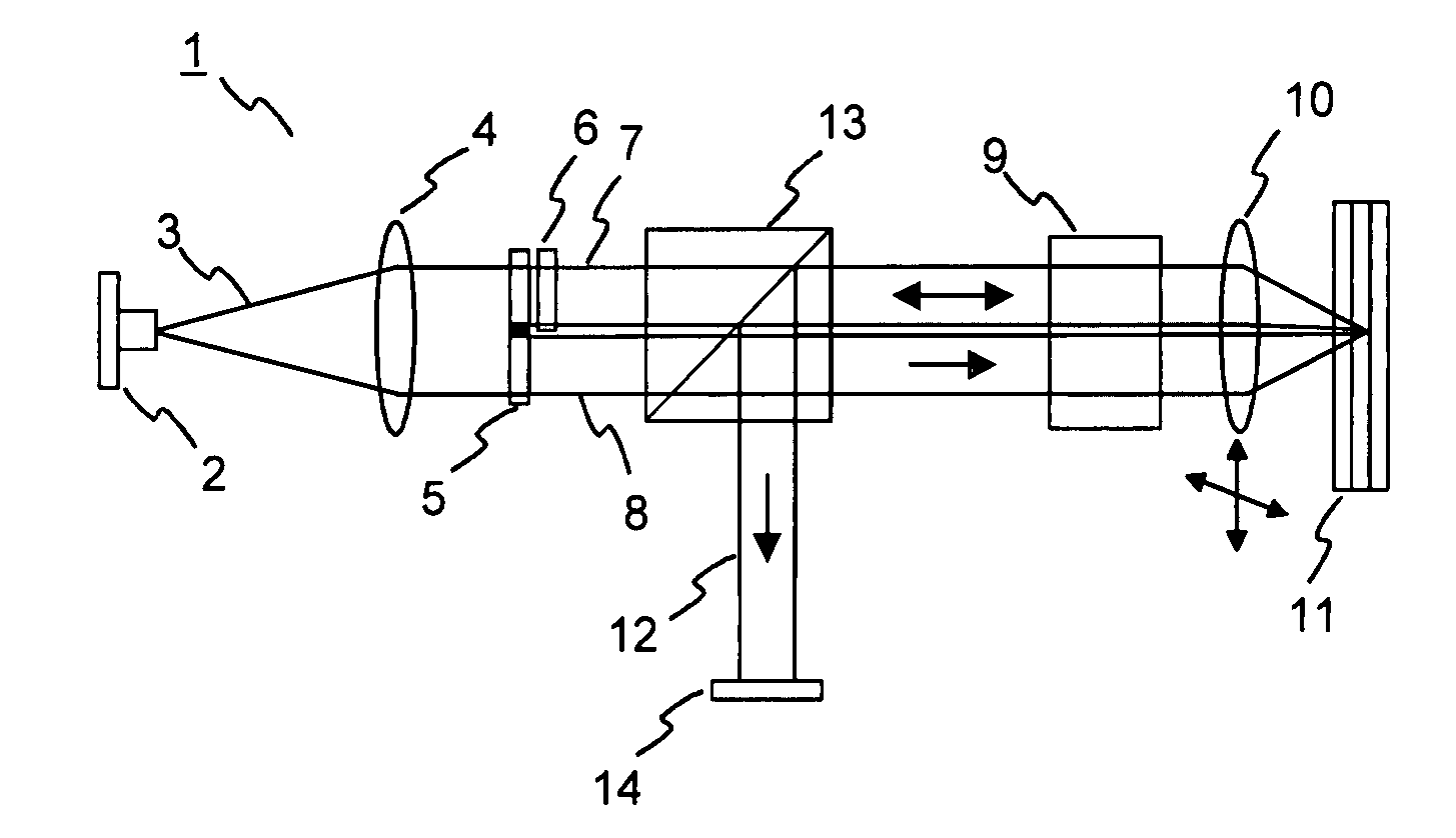
[0024]In holographic data storage digital data are stored by recording the interference pattern produced by the superposition of two coherent laser beams. An exemplary setup of an apparatus 1 for reading from and / or writing to holographic storage media is shown in FIG. 1. A source of coherent light, e.g. a laser diode 2, emits a light beam 3, which is collimated by a collimating lens 4. The light beam 3 is then divided into two separate light beams 7, 8. In the example the division of the light beam 3 is achieved using a first beam splitter 5. However, it is likewise possible to use other optical components for this purpose. A spatial light modulator (SLM) 6 modulates one of the two beams, the so called “object beam”7, to imprint a 2-dimensional data pattern. Both the object beam 7 and the further beam, the so called “reference beam”8, are focused into a holographic storage medium 11, e.g. a holographic disk, by an objective lens 10. At the intersection of the object beam 7 and the ...


PUM

PropertyMeasurementUnit
thickaaaaaaaaaa
grating periodaaaaaaaaaa
fixed distanceaaaaaaaaaa

Abstract

The present invention relates to a beam shifting element and to an apparatus for reading from and/or writing to optical storage media using in such a beam shifting element.
According to the invention, the beam shifting element has at least a first optical element for deflecting an incoming light beam by a first angle and a second optical element for deflecting the light beam coming from the first optical element by a second angle opposite to the first angle, wherein the first optical element and the second optical element are optical elements with an adjustable deflection angle.

Description

FIELD OF THE INVENTION[0001]The present invention relates to an apparatus for reading from and / or writing to optical storage media, such as holographic storage media, and more specifically to a beam shifting element for use in such an apparatus.BACKGROUND OF THE INVENTION[0002]In holographic data storage digital data are stored by recording the interference pattern produced by the superposition of two coherent laser beams, where one beam, the so-called ‘signal beam’, is modulated by a spatial light modulator and carries the information to be recorded. The second beam serves as a reference beam. The interference pattern leads to modifications of specific properties of the storage material, which depend on the local intensity of the interference pattern. Reading of a recorded hologram is performed by illuminating the hologram with the reference beam using the same conditions as during recording. This results in the reconstruction of the recorded signal beam.[0003]One advantage of holo...

Claims


Application Information

Patent Timeline
Patent Type & Authority Applications(United States)
IPC IPC(8): G11B7/00G11B7/135
CPCG02B26/0808G02B26/0875G11B7/0065G11B7/1369G11B7/0901G11B7/1359G11B7/083
Inventor KNITTEL, JOACHIM
Owner THOMSON LICENSING SA
Why Eureka
Try Eureka