
Methods and Apparatus for Carbon Dioxide Removal from a Fluid Stream

a technology of carbon dioxide and fluid stream, which is applied in the direction of liquid-gas reaction process, hydrogen sulfide, chemical/physical process, etc., can solve the problems of high capital cost associated with removing impurities, high capital cost of wgs reaction, and large amount of energy required to generate excessive steam for wgs reaction, etc., to achieve high efficiency, reduce or eliminate other system components, and increase system efficiency

Inactive Publication Date: 2008-05-15
GENERAL ELECTRIC CO
View PDF41 Cites 18 Cited by
  • Summary
  • Abstract
  • Description
  • Claims
  • Application Information

AI Technical Summary

Problems solved by technology

The commercialization of known ‘coal-to-hydrogen (H2) and electricity’ technologies (coal gasification-based polygeneration plants or IGCC power plants) has been hampered by the high capital costs associated with removing the impurities.
Also, in order to attain the desired CO conversion, highly excessive amounts of steam are generally introduced to the syngas stream in order to drive the WGS reaction to near completion.
As a result, the WGS reaction demands large amount of energy to generate the excessive amount of steam that the reaction requires.
The cost of pre-combustion CO2 capture using commercially available technologies such as absorbent based technologies can be as high as $40 / ton, which, although is much lower than the cost of post-combustion capture, is still much too high for carbon emissions reduction applications.
Furthermore, carbon dioxide capture is generally estimated to represent three-fourths of the total cost of a carbon capture, storage, transport, and sequestration system.

Method used


Image

  • Methods and Apparatus for Carbon Dioxide Removal from a Fluid Stream
  • Methods and Apparatus for Carbon Dioxide Removal from a Fluid Stream
  • Methods and Apparatus for Carbon Dioxide Removal from a Fluid Stream

Examples


examples

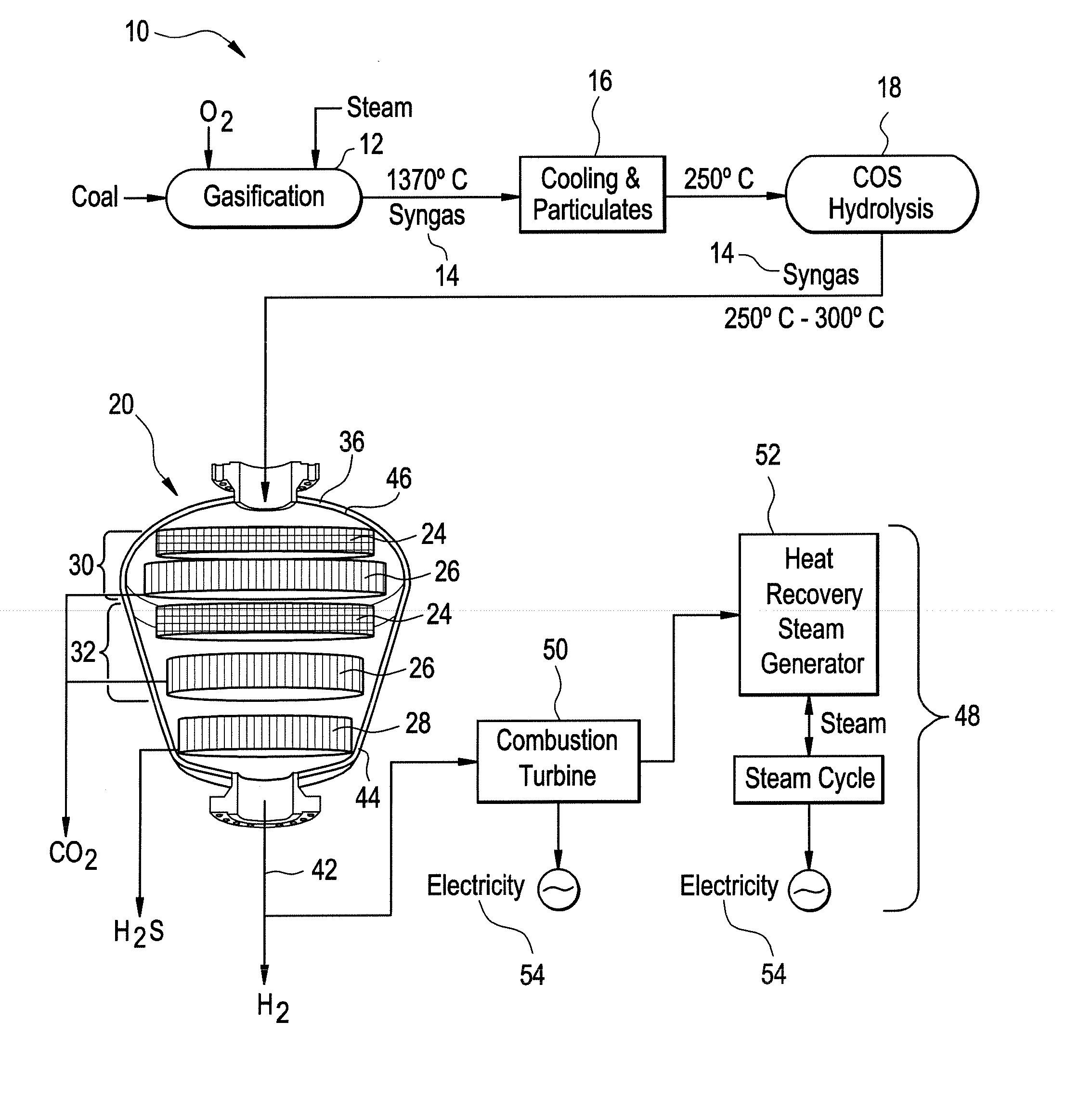
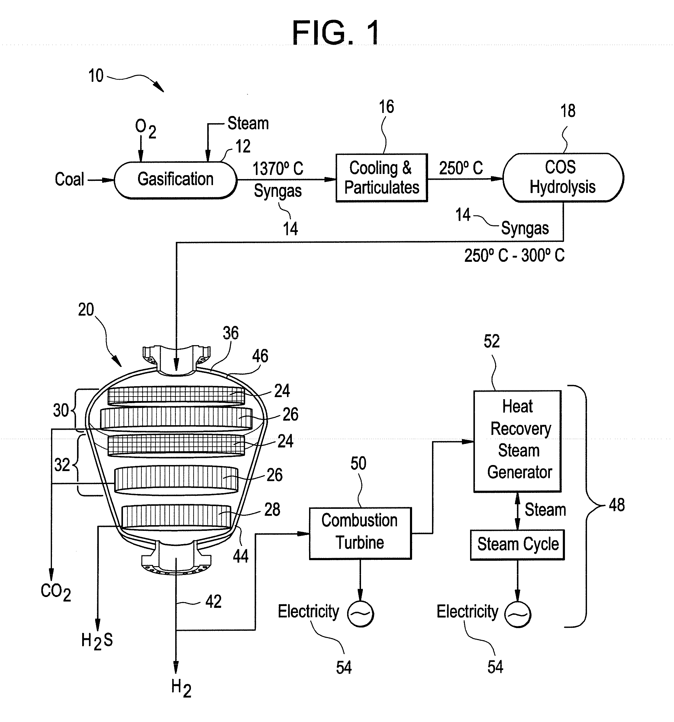
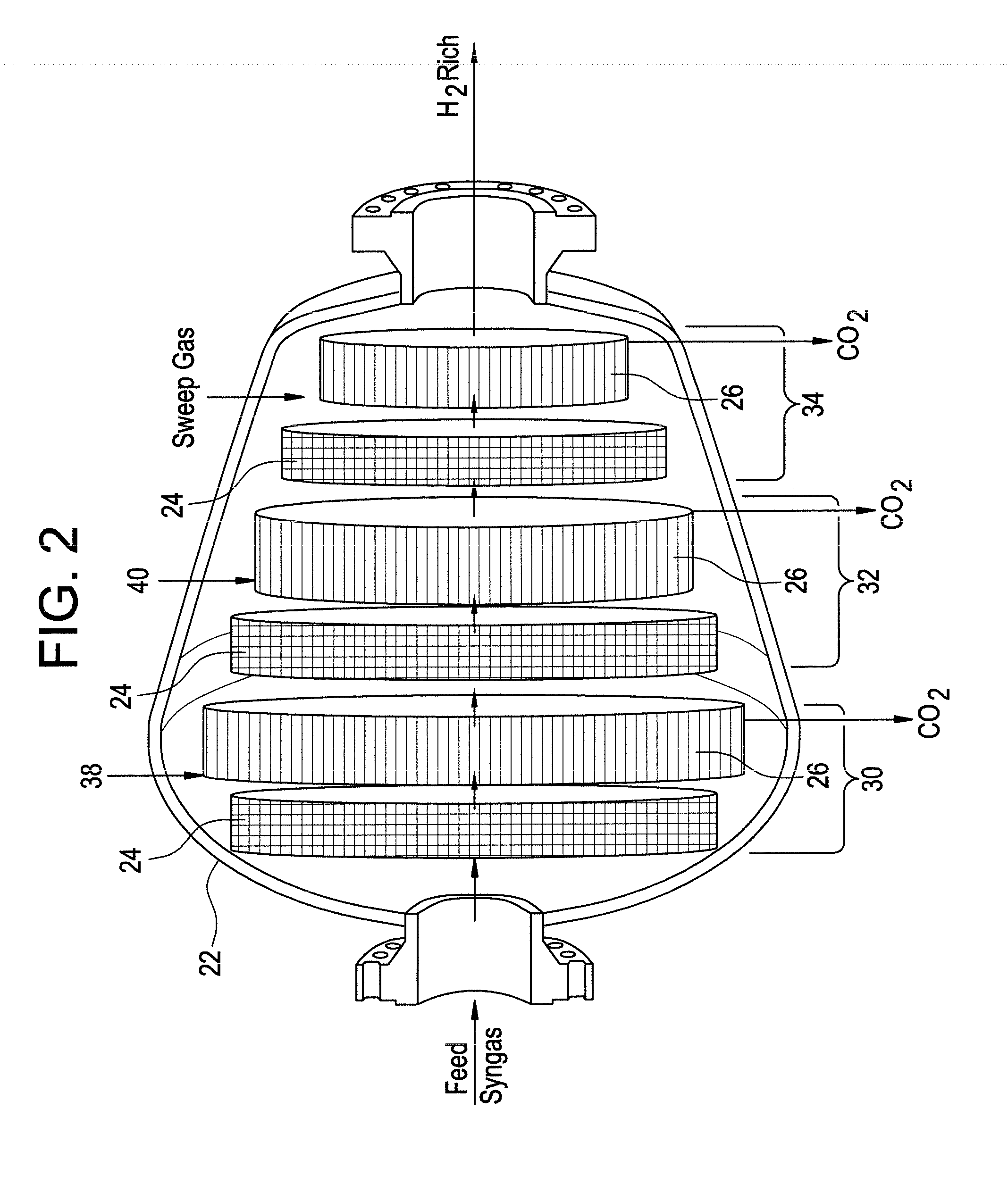
[0041]Two reactors designs were calculated to determine the effect of a single removal portion (Reactor 1) versus multiple conversion-removal portions (Reactor 2). For each reactor, Reactor 1 and Reactor 2, the membrane permeability for CO2 was 10,000 Barrer, the selectivity of CO2 over H2 was 25, the thickness of the membrane functional layer was 1 micrometer, the internal diameter of each membrane tube was 1 centimeter (cm), each membrane section was divided into 8 parallel trains, and the inlet syngas molar flow rate was 4,000 kilomoles per hour (kmol / hr) with 29 volume percent (vol %) CO, 31 vol % H2O, 12 vol % CO2, and 26 vol % H2, while the syngas stream pressure was 30 bar and temperature was 350° C. The outlet temperature was about 250° C.

[0042]It is noted that the permeability is the gas flow rate multiplied by the thickness of the material, divided by the area and by the pressure difference across the material. To measure this quantity, the barrer is the permeability repre...


PUM

PropertyMeasurementUnit
temperatureaaaaaaaaaa

Abstract

An apparatus for producing hydrogen gas wherein the apparatus includes a reactor. In one embodiment, the reactor includes at least two conversion-removal portions. Each conversion-removal portion comprises a catalyst section configured to convert CO in the stream to CO2 and a membrane section located downstream of and in flow communication with the catalyst section. The membrane section is configured to selectively remove the CO2 from the stream and to be in flow communication with a sweep gas.

Description

STATEMENT REGARDING FEDERALLY SPONSORED RESEARCH & DEVELOPMENT[0001]This invention was made with Government support under contract number DOE NETL DE-FC26-05NT42451 awarded by the U.S. Department of Energy. The Government may have certain rights in the invention.BACKGROUND[0002]This application relates generally to gas separation processes and apparatus, and more particularly, to CO2 sequestration.[0003]The application of syngas conversion and purification, e.g., after the syngas is generated from coal gasification processes, can be used for integrated gasification combined cycle (IGCC) power plants for electricity production from coal, and IGCC-based polygeneration plants that produce multiple products such as hydrogen and electricity from coal, and is useful for plants that include carbon dioxide separation. It is also applicable to purification of other hydrocarbon-derived syngas which can be used for electricity production or polygeneration, including syngas derived from natural...

Claims


Application Information

Patent Timeline
Patent Type & Authority Applications(United States)
IPC IPC(8): B01D53/62C01B32/50
CPCC01B2203/0485C01B2203/0475C01B2203/84C01B2203/86Y02C10/04Y02C10/10B01J19/2475B01J19/2485B01J2219/00108B01J2219/00123B01J2219/1946C01B3/16C01B3/501C01B2203/0283C01B2203/0405C01B2203/1064Y02C20/40Y02P30/00Y10S48/05
Inventor WEI, WEIRUUD, JAMES ANTHONYKU, ANTHONY YU-CHUNGRAMASWAMY, VIDYALIU, KE
Owner GENERAL ELECTRIC CO
Learn More