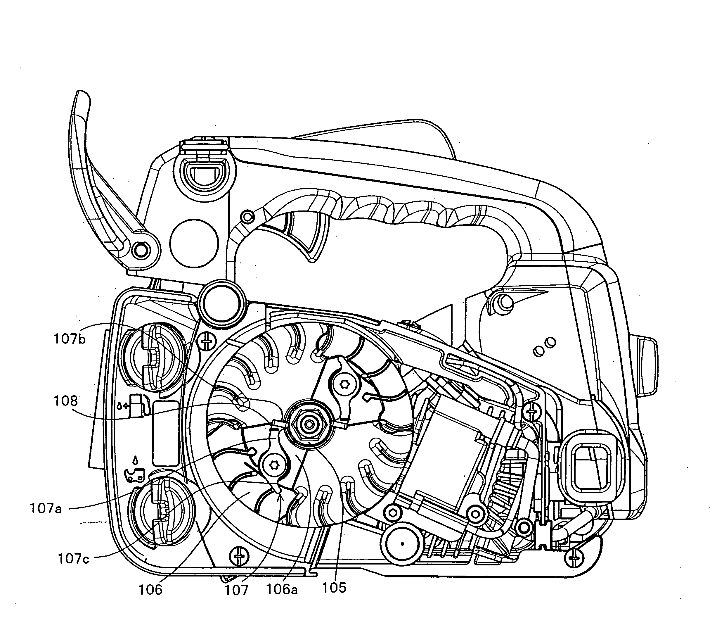
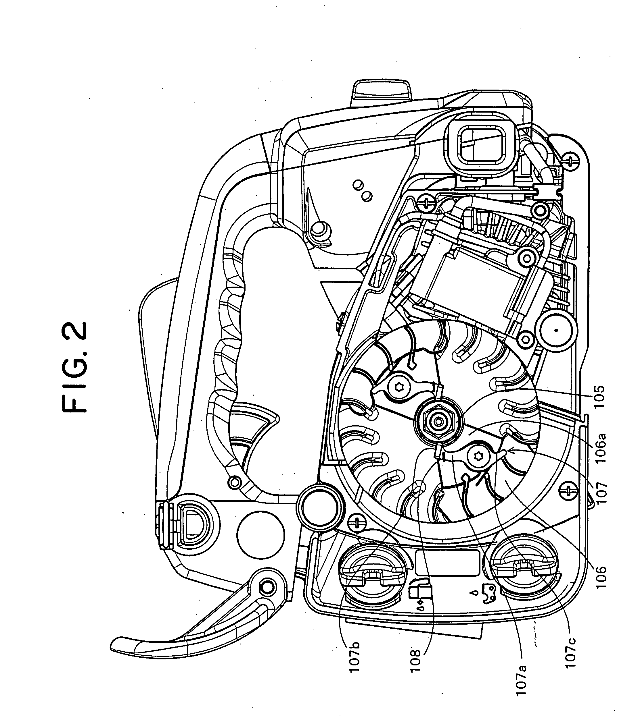
[0016]The shape of the lever-shaped engaging and disengaging portion of the
centrifugal clutch mechanism is formed by concaving a side surface facing to the ratchet tooth of the second ratchet portion in a direction away from the ratchet tooth from the pivot portion to the engaging and disengaging pawl portion in the tip end. Accordingly, even if the engaging and disengaging pawl portion is stopped in the state of running on the ratchet tooth or in the state of getting over the ratchet tooth, at a time of starting the engine, the engagement surface of the engaging and disengaging pawl portion is changed to the posture looking into the engagement surface of the ratchet tooth in accordance with the rotation of the ratchet tooth, and the concave portion of the lever-shaped engaging and disengaging member thereafter strides over the ratchet. In order to brace the ratchet tooth to be engaged in the posture, the engagement surfaces of the ratchet tooth and the engaging and disengaging pawl portion are brought into contact with each other. As mentioned above, the engagement surface of the engaging and disengaging pawl portion securely faces to the engagement surface of the ratchet tooth just before the engagement. For this reason, a surface engagement is achieved, and a local collision between the pawl tip and the tooth tip is avoided, so that the pawl tip and the tooth tip are not broken. Since the engagement at this time is achieved by the surface engagement, an
impact force at a time of engaging is not concentrated to one point, and it is possible to do away with the deformation of the engaging and disengaging pawl portion and the ratchet tooth.
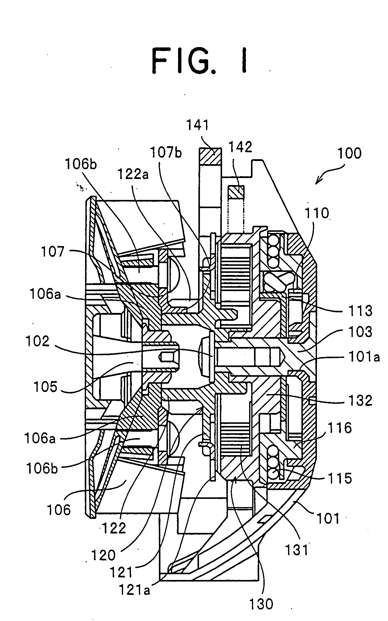
[0017]In general, the power spring
barrel drum is supported to a main shaft via a bearing type one-way
clutch so as to only allow the rotation of the power spring in the force accumulating direction, or a ratchet mechanism is used. The bearing type one-way
clutch and the ratchet mechanism mentioned above are basically provided for accumulating the force in the power spring accommodated in the inner portion of the power spring
barrel drum. On the other hand, there have been conventionally an engine starting device of a type excluding the bearing type one-way
clutch and the ratchet mechanism, directly transmitting the drive of the rotation drive portion to the rotation driven portion via the
barrel drum and the power spring and automatically starting the engine at a time when the power is accumulated in the power spring over the maximum load of the engine. In accordance with the engine starting device of this type, the engine can be started at a
stroke, for example, in the case of starting the engine on the basis of the pulling operation of the recoil rope. For this reason, this engine starting device is favorite of those skilled in the art or the like.
[0018]The present invention is configured such that in addition to the matter that it is possible to release the accumulated force of the power spring so as to start the engine by operating the engaging and disengaging lever from the external portion as mentioned above so as to detach the engagement between the first ratchet portion of the rotation driven portion and the engaging and disengaging lever, it is possible to directly transmit the accumulated force stored in the power spring to the rotation driven portion so as to start the engine. Accordingly, the configuration is made such that a third ratchet portion is formed in the power spring barrel drum, and the engagement between the second engaging and disengaging lever and the power spring barrel drum is detached by actuating the engaging and disengaging lever in accordance with the external operation approximately the same time of detaching the engagement with the first rotation ratchet portion. As mentioned above, when switching to the type directly transmitting the drive of the rotation drive portion to the rotation drive portion via power spring barrel drum and the power spring, the power spring barrel drum is rotated while accumulating the force in the power spring on the basis of the drive of the rotation drive portion, and a part of the accumulated force of the power spring is released so as to slowly rotate the first ratchet portion of the rotation driven portion concurrently, wherever the engaging and disengaging pawl portion of the
centrifugal clutch mechanism stops at a time of the preceding engine stop. Consequently, the ratchet tooth is brought into contact with the engaging end disengaging pawl portion of the centrifugal clutch mechanism on the small
impact force at a time of the rotation so as to be engaged. Accordingly, when switching to this type, the pawl tip and the tooth tip are not broken.
[0019]In this case, when the engine stops, the stop position of the first ratchet portion of the rotation drive portion is not necessarily constant in addition to the stop position of the engaging and disengaging pawl portion as mentioned above. Accordingly, in the case where the engine is started by engaging the engaging and disengaging lever with the ratchet tooth of the first ratchet portion, and detaching the engaging and disengaging lever after accumulating a desired accumulated force in the force accumulating power spring, the first ratchet portion is slightly rotated in the accumulated force releasing direction via the power spring if the power spring barrel drum is rotated in the force accumulating direction. On the other hand, as mentioned above, the stop position of the engaging and disengaging pawl portion in the engine side is not constant at a time of the engine stop.
[0020]When the engine is started by detaching the engagement between the engaging and disengaging lever and the first ratchet portion as mentioned above after accumulating the force in the force accumulating power spring, there is a
high probability that the first ratchet portion is rotated even slightly as mentioned above. Accordingly, if the ratchet teeth of the first ratchet portion and the second ratchet portion are arranged at a predetermined
phase difference, the ratchet tooth of the second ratchet portion rotating in accordance with the rotation of the first ratchet portion previously gets close to the engaging and disengaging pawl portion in the engine side away from the ratchet tooth. Then, a distance of engagement between the first ratchet portion and the engaging end disengaging pawl portion corresponding to a part of the centrifugal clutch mechanism becomes shorter at a time of starting the engine, and a
kinetic energy until both the elements are engaged becomes smaller.
[0021]In addition, since an angle of slope is applied to the ratchet tooth of the first ratchet portion, a wedge effect is generated in the engagement between the engaging and disengaging lever and the first ratchet portion, and it is possible to firmly engage. Further, in the case where the engaging and disengaging lever is formed by an L-shaped sheet
metal, and an engaging pawl is formed by bending a leading end portion thereof perpendicularly, it is possible to make an engaging width in a
crank axial direction of the engagement portion larger on the basis of the length of the bent portion, and it is possible to allow the motion in the
crank axial direction to some extent in the engagement portion between the first ratchet portion and the engaging and disengaging pawl portion. Accordingly, it is possible to prevent the engagement from being cancelled by the small external force.

