
High strength and sagging resistant fin material

Active Publication Date: 2008-05-22
GRAENGES SWEDEN AB
View PDF19 Cites 22 Cited by
  • Summary
  • Abstract
  • Description
  • Claims
  • Application Information

AI Technical Summary

Problems solved by technology

However, the as delivered strip had an elongation, A50mm, of only 1.5% and liquid core penetration during brazing was not considered.
The material is used in vacuum brazing and contains high amounts of Mg, 0.3-1.5%, that are not acceptable for brazing in CAB furnaces.
Without the high Mg content this material will not provide the desired microstructure required for the high post braze strength.
A material with such high Mg content will not give the low susceptibility to liquid core penetration required by manufacturers of heat exchangers today.
Also the Mn content is too low to achieve the higher strengths required when down gauging to thinner material.
It has been shown in the practical testing of the material produced according to the previously known methods that the properties of the aluminium strip are insufficient for certain applications when the manufacturers need to down gauge.

Method used


Image

  • High strength and sagging resistant fin material
  • High strength and sagging resistant fin material

Examples


example 1

[0034]Two ingots of material A1 and A2 with a composition of 0.8-0.9% Si, 0.2% Fe, 1.6% Mn, 0.11-0.12% Zr, 1.5-1.6% Zn and other elements each less than 0.05% were DC-cast pre-heated below 550° C. and hot rolled with a total hot reduction of 99% prior to cold rolling. Material A1 was directly cold rolled to final gauge and annealed at different temperatures. Some material was fully soft annealed to 0 temper, some was recovery annealed to H24 temper and some was not annealed at all giving H18 temper. Material A2 was recrystallisation annealed before final cold rolling to H14 temper. All samples were exposed to a heat treatment to simulate brazing at 600° C.

[0035]The properties are shown in Table 1.

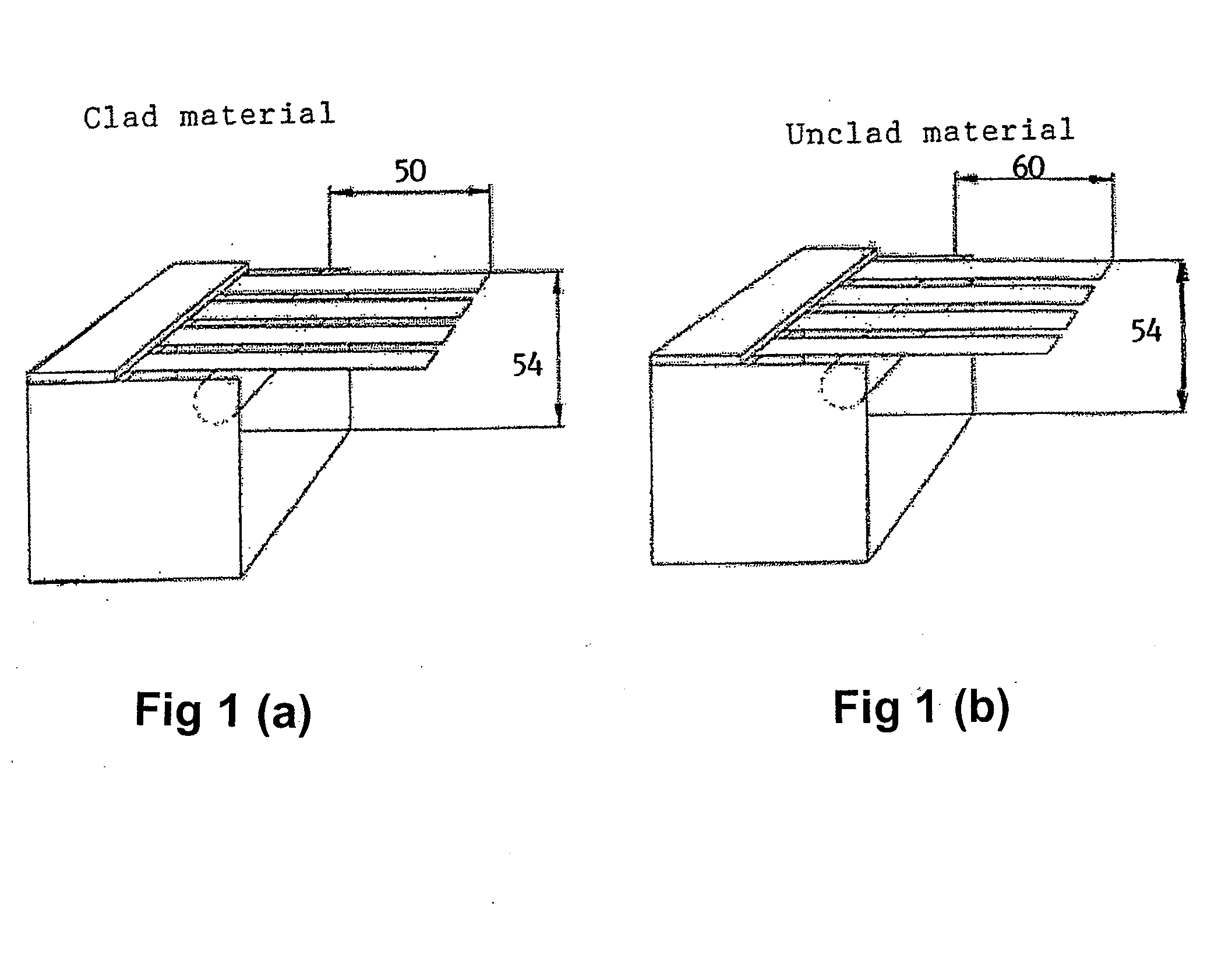
[0036]The sagging resistance was measured according to the following method: The material is mounted in a special rig as shown in FIG. 1. Samples 15 mm wide were cut across the rolling direction and at least 90 mm along the rolling direction. Four samples were mounted in the rig. The cantil...

example 2

[0040]Three ingots from the very same charge, with composition of 0.8% Si, 0.2% Fe, 1.6% Mn, 0.12% Zr, 1.6% Zn and other elements each less than 0.05%, were pre heated at different temperatures prior to hot rolling to improve the delivery formability and sagging resistance during brazing. The final temperatures and total heating times for the different ingots were for B1-457° C. / 11 hours, B2-490° C. / 15 hours, B3-540° C. / 21 hours. The materials were hot rolled, cold rolled and recovery annealed to H24 temper. The properties of 0.1 mm final strip are given in Table 2.

TABLE 2Properties measured for material B. The sagging resistance was measuredusing a cantilever beam length of 60 mm.Pre heatingSaggingTemp / totalAs deliveryAs deliverydistanceMaterialtimeRp0.2 [MPa]A50mm [%][mm]B1457° C. / 11 hours1843.822B2490° C. / 15 hours1756.818B3540° C. / 21 hours1974.430

[0041]The results show that there is an optimum temperature and time for preheating prior to hot rolling to achieve the best combinatio...

example 3

[0042]The effect of delivery temper was investigated on braze clad strip of a material C with following composition:

[0043]Core Mn=1.6%, Si=0.8%, Fe=0.2%, Zn=1.5%, Zr=0.11%, other elements each less than 0.05%. Braze clad Si=7.7%, Fe=0.1%, other elements each less than 0.05%. The material is clad with 10% on each side. Cladding was carried out during hot rolling.

[0044]The material was DC-cast, followed by pre heating below 550° C., hot rolling to 4 mm and cold rolling to 0.10 mm final thickness. The material in H14 condition was fully soft annealed at 0.17 mm intermediate gauge. All samples in this example are taken from the identical mother coil. The different samples could be taken by splitting the coil in different parts.

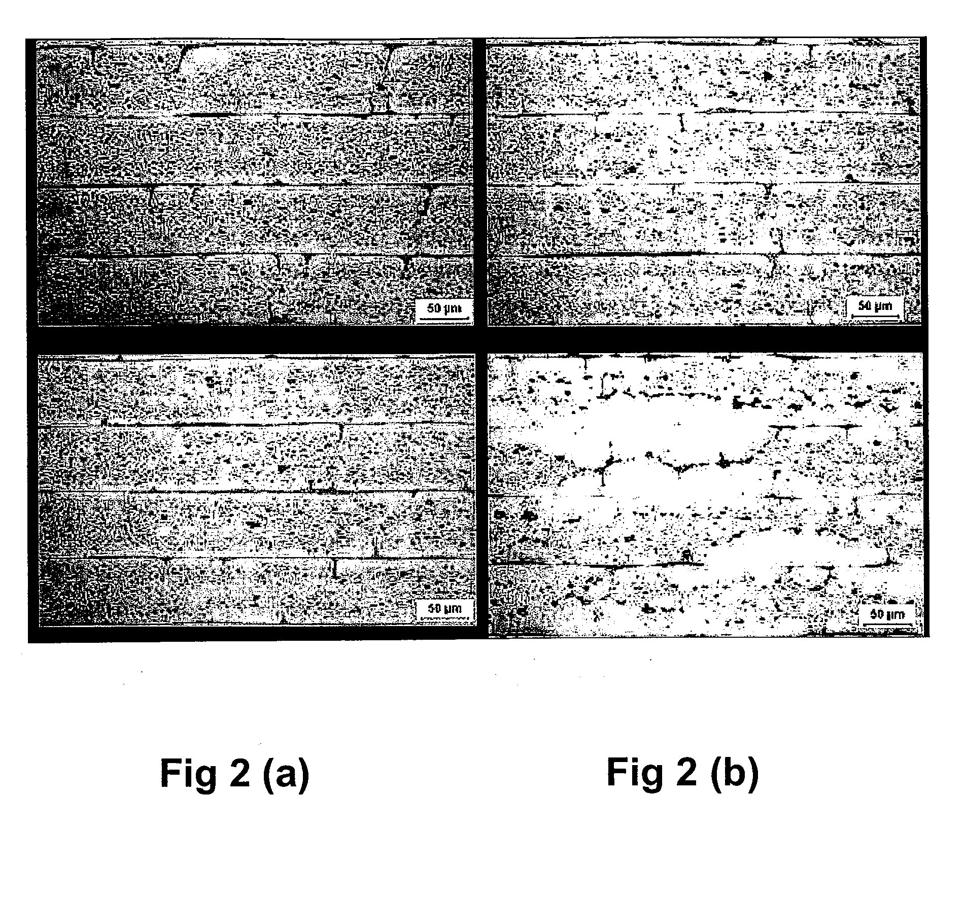
[0045]To measure the particle density of the material sections were cut in the longitudinal, ND-RD, plane of the strip. The sections were mechanically polished using Struers OP-S suspension, containing 0.04 μm colloidal silica, in the last preparation step. The ar...


PUM

PropertyMeasurementUnit
Temperatureaaaaaaaaaa

Abstract

The present invention provides a method for producing AlMn strip or sheet for making components by brazing, as well as the products obtained by said method. In particular this method is related to fin materials used in heat exchangers. The fins can be delivered with or without a cladding depending on application.Rolling slabs are produced from a melt which contains 0.3-1.5% Si, ≦0.5% Fe, ≦0.3% Cu, 1.0-2.0% Mn, ≦0.5% Mg, ≦4.0% Zn, ≦0.3% each of elements from group IVb, Vb, or VIb elements, and unavoidable impurity elements, as well as aluminium as the remainder in which the rolling slabs prior to hot rolling are preheated at a preheating temperature of less than 550° C., preferably between 400 and 520° C., more preferably between 450 and 520° C. to control the number and size of dispersoid particles, and the preheated rolling slab is hot rolled into a hot strip. The strip is thereafter cold rolled into a strip with a total reduction of at least 90%, and the cold rolled strip is heat treated to obtain a 0.2% proof stress value that is 50-90% of its proof stress value in the as cold rolled condition to a proof stress value in the range between 100 and 200 MPa. The strip may alternatively be produced by twin-roll strip casting.The composition of the melt tailors the microstructure development during the complete processing to give the desired post braze properties and performance during brazing in combination with adequate delivery properties of the strip. In particular the high post braze strength combined with a good sagging resistance and low susceptibility to liquid core penetration during brazing, as well as a relatively good formability in the delivery condition prior to fin forming.

Description

[0001]This application claims priority under 35 U.S.C. 119 to Sweden Application No. 0602165-3, filed Oct. 13, 2006, which application is incorporated herein by reference and made a part hereof.BACKGROUND[0002]The present invention relates to a method for producing AlMn strip or sheet for producing components by brazing, as well as the products obtained by said method. In particular this method is related to fin materials used in heat exchangers. The fins can be delivered with or without a braze cladding depending on application.[0003]A challenge today is to manufacture light-weight components for the automotive market. A lot of research is therefore directed to reduce the weight of heat exchangers by using thinner strip without sacrificing, but instead often improving, other product and manufacturing properties. To be able to do this it is necessary to create new materials with higher post braze strength compared to the alloys presently used but still with adequate corrosion proper...

Claims


Application Information

Patent Timeline
IPC IPC(8): C22C21/16C22F1/04
CPCB22D11/008B23K35/0238B23K35/286B23K2201/14F28F21/084B32B15/016C22C21/00C22F1/04B32B15/01B23K2101/14F28F21/08
Inventor OSKARSSON, ANDERSEKSTROM, HANS-ERIKWESTERGARD, RICHARDTANGEN, STIAN
Owner GRAENGES SWEDEN AB
Learn More