Ai-ni-la system ai-based alloy sputtering target and process for producing the same

a technology of ai-ni-la system and ai-based alloy, which is applied in the direction of vacuum evaporation coating, electrolysis components, coatings, etc., can solve the problems of high production cost, high production cost, and deterioration of fpd yield and operation performance, so as to reduce the splash

Active Publication Date: 2008-05-29
KOBE STEEL LTD +1
View PDF24 Cites 63 Cited by
  • Summary
  • Abstract
  • Description
  • Claims
  • Application Information

AI Technical Summary

Benefits of technology

[0011]The invention was carried out in view of the above-mentioned circumstances and intends to provide a technology that can reduce the splashes, in particular, the initial splashes generated when a Ni and La-containing Al—Ni—La system Al-based alloy sputtering target is used to deposit a film.

Problems solved by technology

However, in a method of interposing a barrier metal layer such as mentioned above, there is a problem in that a production process becomes troublesome to be high in the production cost.
However, when the sputtering power is increased, sputtering defects such as splashes (fine melt particles) are caused to generate defects in the interconnection film; accordingly, harmful effects such as deteriorating the yield and operation performance of the FPDs are caused.
In particular, the initial splashes occurring in an initial stage of the sputtering deteriorate the yield of FPDs and thereby cause a serious problem.
However, the splash inhibition technologies disclosed in JP-A-10-147860, JP-A-10-199830, JP-A-11-293454 or JP-A-2001-279433 cannot sufficiently effectively inhibit the initial splashes from occurring.
Furthermore, in an Al-based alloy sputtering target that is used to form a thin film of, among Al-based alloys, an Al—Ni-rare earth element alloy useful as a wiring material capable of directly connectable with an electroconductive oxide film that constitutes a pixel electrode, in particular, an Al—Ni—La system Al-based alloy, a technology that can overcome the above-mentioned problems has not yet been proposed.

Method used


Image

  • Ai-ni-la system ai-based alloy sputtering target and process for producing the same
  • Ai-ni-la system ai-based alloy sputtering target and process for producing the same
  • Ai-ni-la system ai-based alloy sputtering target and process for producing the same

Examples


example 1

[0104]With Al-based alloys having various compositions shown in table 1, according to the following spray forming method, Al-based alloy performs (density: substantially 50 to 60%) were obtained.

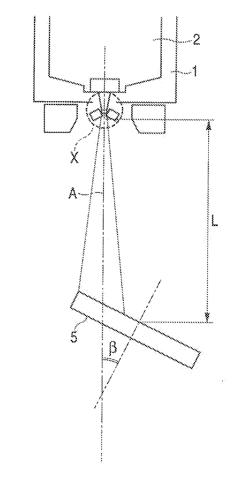
[0105](Spray forming conditions)

[0106]Melting temperature: 750 to 1100° C. (refer to Table 1)

[0107]Gas / metal ratio: 5 to 7 Nm3 / kg (refer to Table 1)

[0108]Spray distance: 800 to 1300 mm

[0109]Gas atomizer outlet angle (α): 70

[0110]Collector angle (β): 35°

[0111]Thus obtained perform was sealed in a capsule, followed by deaerating, further followed by applying a hot isostatic pressing (HIP) to an entirety of the capsule, whereby an Al—Ni—La system Al-based alloy dense body was obtained. The HIP process was carried out at a HIP temperature of 550° C., under a HIP pressure of 85 MPa for the HIP time of 2 hours.

[0112]Thus obtained dense body was forged into a slub metal material, followed by rolling so that a plate thickness may be substantially same as that of a final product (target), further fol...


PUM

PropertyMeasurementUnit
average particle diameteraaaaaaaaaa
temperatureaaaaaaaaaa

Abstract

The invention relates to an Al—Ni—La system Al-based alloy sputtering target comprising Ni and La, wherein, when a section from (¼)t to (¾)t (t: thickness) in a cross section vertical to a plane of the sputtering target is observed with a scanning electron microscope at a magnification of 2000 times, (1) a total area of an Al—Ni system intermetallic compound having an average particle diameter of 0.3 μm to 3 μm with respect to a total area of the entire Al—Ni system intermetallic compound is 70% or more in terms of an area fraction, the Al—Ni system intermetallic compound being mainly composed of Al and Ni; and (2) a total area of an Al—La system intermetallic compound having an average particle diameter of 0.2 μm to 2 μm with respect to a total area of the entire Al—La system intermetallic compound is 70% or more in terms of an area fraction, the Al—La system intermetallic compound being mainly composed of Al and La.

Description

FIELD OF THE INVENTION[0001]The present invention relates to an Al—Ni—La system Al-based alloy sputtering target containing Ni and La and a process for producing the same. In more detail, it relates to an Al—Ni—La system Al-based alloy sputtering target that can, when a thin film is deposited by the use of a sputtering target, reduce the number of initial splashes generated at an initial stage of sputtering, and a process for producing the same.BACKGROUND OF THE INVENTION[0002]An Al-based alloy, being low in the electrical resistivity and easy to process, is widely used in a field of flat panel displays (FPD) such as liquid crystal displays (LCD), plasma display panels (PDP), electroluminescent displays (ELD) and field emission displays (FED) and is used as materials for interconnection films, electrode films and reflective electrode films.[0003]For instance, an active matrix type liquid crystal display includes a thin film transistor (TFT) that is a switching element, a pixel elect...

Claims


Application Information

Patent Timeline
Patent Type & Authority Applications(United States)
IPC IPC(8): C23C14/50B05D3/00
CPCC22C21/00C23C14/3414C23C4/121C23C4/08C23C4/123B22F9/082B22F3/115B22F3/15B22F3/17B22F3/18B22F2998/10H01J37/3426H01J37/3429
Inventor EHIRA, MASAYATAKAGI, KATSUTOSHIKUGIMIYA, TOSHIHIROYONEDA, YOICHIROGOTOU, HIROSHI
Owner KOBE STEEL LTD
Why Eureka
Try Eureka