

Method for producing optical film
a production method and technology of optical film, applied in the direction of other domestic articles, protein coatings, protein adhesives, etc., can solve the problems of cellulose ester leveling and inferior optical properties to films produced by the solution cast method, and achieve the effect of small fluctuation of retardation
- Summary
- Abstract
- Description
- Claims
- Application Information
AI Technical Summary
Benefits of technology
Problems solved by technology
Method used
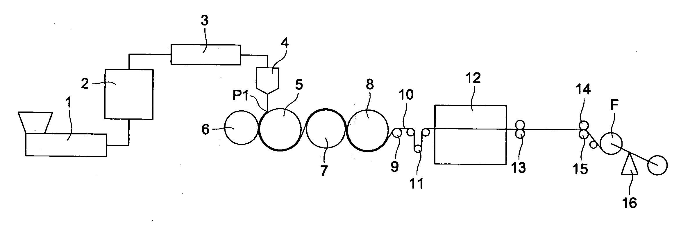
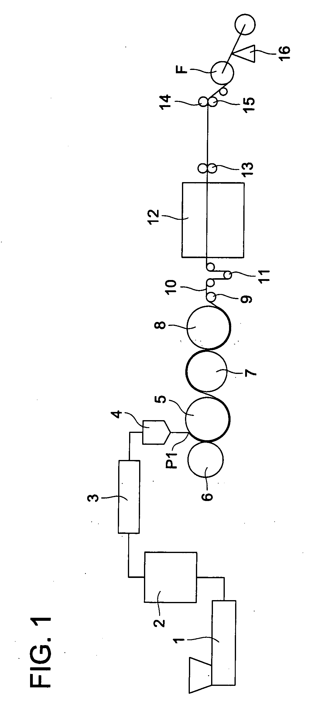
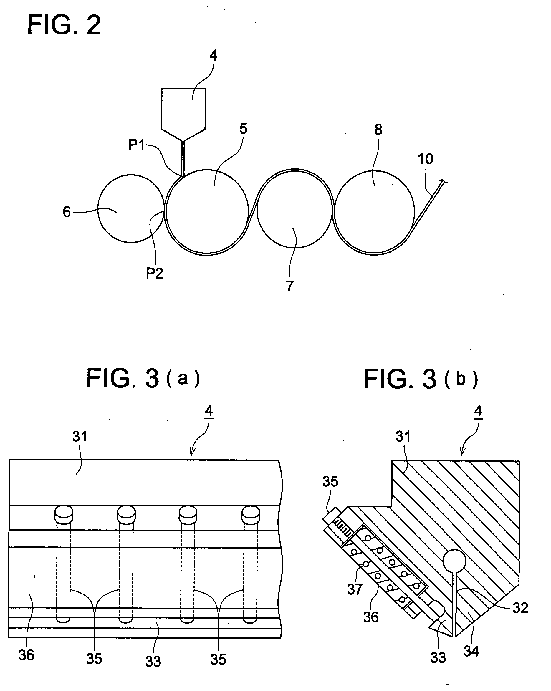
Image

Examples
example 1
Synthesis of Cellulose Ester
[0321]Six kinds of cellulose ester were synthesized in which substituting degree of acetyl group, that of propionyl group and that of butyryl group were varied as follows. The synthesis was carried out referring Example B in WO 92 / 05213 and controlling the adding amount of propionic acid, butyric acid or acetic acid.
[0322]C-1 Acetyl group substitution degree: 1.30[0323]Propionyl group substitution degree: 1.30[0324]Total acyl group substitution degree: 2.60
[0325]C-2 Acetyl group substitution degree: 1.40[0326]Propionyl group substitution degree: 1.40[0327]Total acyl group substitution degree: 2.80
[0328]C-3 Acetyl group substitution degree: 1.30[0329]Propionyl group substitution degree: 1.25[0330]Total acyl group substitution degree: 2.55
[0331]C-4 Acetyl group substitution degree: 1.50[0332]Propionyl group substitution degree: 1.20[0333]Total acyl group substitution degree: 2.70
[0334]C-5 Acetyl group substitution degree: 0.20[0335]Propionyl group substitut...
example 2
Preparation of Polarization Plate and Evaluation
[0398]The above-prepared polarization protection films 101 to 156 were subjected to the following alkali saponifying treatment to prepare polarization plates. Then the polarization plates were each built-in the liquid crystal display, and the contrast and the viewing angle of the display were evaluated.
[0399]>
Saponifying process2M-NaOH50° C.90 secondsWashing processWater30° C.45 secondsNeutralizing processHCl30° C.45 seconds10 weight-percentWashing ProcessWater30° C.45 seconds
[0400]The treatments were carried out in the order of the saponification, washing, neutralization and washing and then drying at 80° C. was performed.
[0401]>
[0402]Long polyvinyl alcohol film having a thickness of 180 μm was immersed in 100 parts by weight of aqueous solution containing 1 part by weight of iodine and 4 parts by weight of boric acid and stretched for 5 times in the transferring direction at 50° C. to prepare a polarization layer. Each of the alkali ...
PUM
| Property | Measurement | Unit |
|---|---|---|
| weight | aaaaa | aaaaa |
| stretching degree | aaaaa | aaaaa |
| viscosity | aaaaa | aaaaa |
Abstract
Description
Claims
Application Information