
Dysprosia stabilized zirconia abradable

Active Publication Date: 2008-05-29
SULZER METCO (US) INC
View PDF11 Cites 18 Cited by
  • Summary
  • Abstract
  • Description
  • Claims
  • Application Information

AI Technical Summary

Benefits of technology

[0013]The invention is directed to ceramic abradable materials used for clearance control between turbine blade tips and the shroud or casing in turbine engines for steam, industrial and aerospace applications. The ceramic abradable in accordance with embodiments of the invention is a generally porous abradable that provides for significantly increased thermal shock resistance as well as the ability of untreated, bare turbine blade tips to cut into the abradable without damaging the tip.
[0014]Embodiments of the present invention provide a ceramic abradable material that comprises dysprosia (Dy2O3) and zirconia (ZrO2). Generally, the material may include dysprosia in the range of about 2 to 50 wt %, with the balance, minus impurities, being zirconia. In accordance with one embodiment of the invention, about 10 wt % of dysprosia is added to zirconia to provide a 10 wt % dysprosia stabilized zirconia or 10 DySZ. The abradable composition according to this embodiment demonstrates a three- to four-fold improvement in thermal shock resistance combined with a significantly improved erosion resistance and abradability as compared to conventional YSZ compositions. In accordance with embodiments of the invention it also provides for the application of the dysprosia stabilized zirconia composition for sealing components in turbine engines.

Problems solved by technology

The result is decreased clearances to levels difficult to achieve otherwise.
Although such standard YSZ materials are basically suited for use as abradable materials, their performance in this application is far from optimum in terms of thermal shock behavior, sintering resistance, and their potential inability to be cut by unshrouded blades having untreated, bare alloy blade tips.
This challenges another important property of the ceramic abradable coating, namely the coating's resistance to spallation during thermal shock loading which generally decreases with increasing coating thickness.
While such abrasive tipping improves the cutting behavior of the blades, it is expensive to apply and an optimized ceramic abradable system should avoid the need for hard tipping by providing improved cuttability or abradability of the seal.

Method used


Image

  • Dysprosia stabilized zirconia abradable
  • Dysprosia stabilized zirconia abradable
  • Dysprosia stabilized zirconia abradable

Examples


Embodiment Construction

[0031]Reference will now be made in detail to the preferred embodiments of the present invention, examples of which are illustrated in the accompanying drawings.

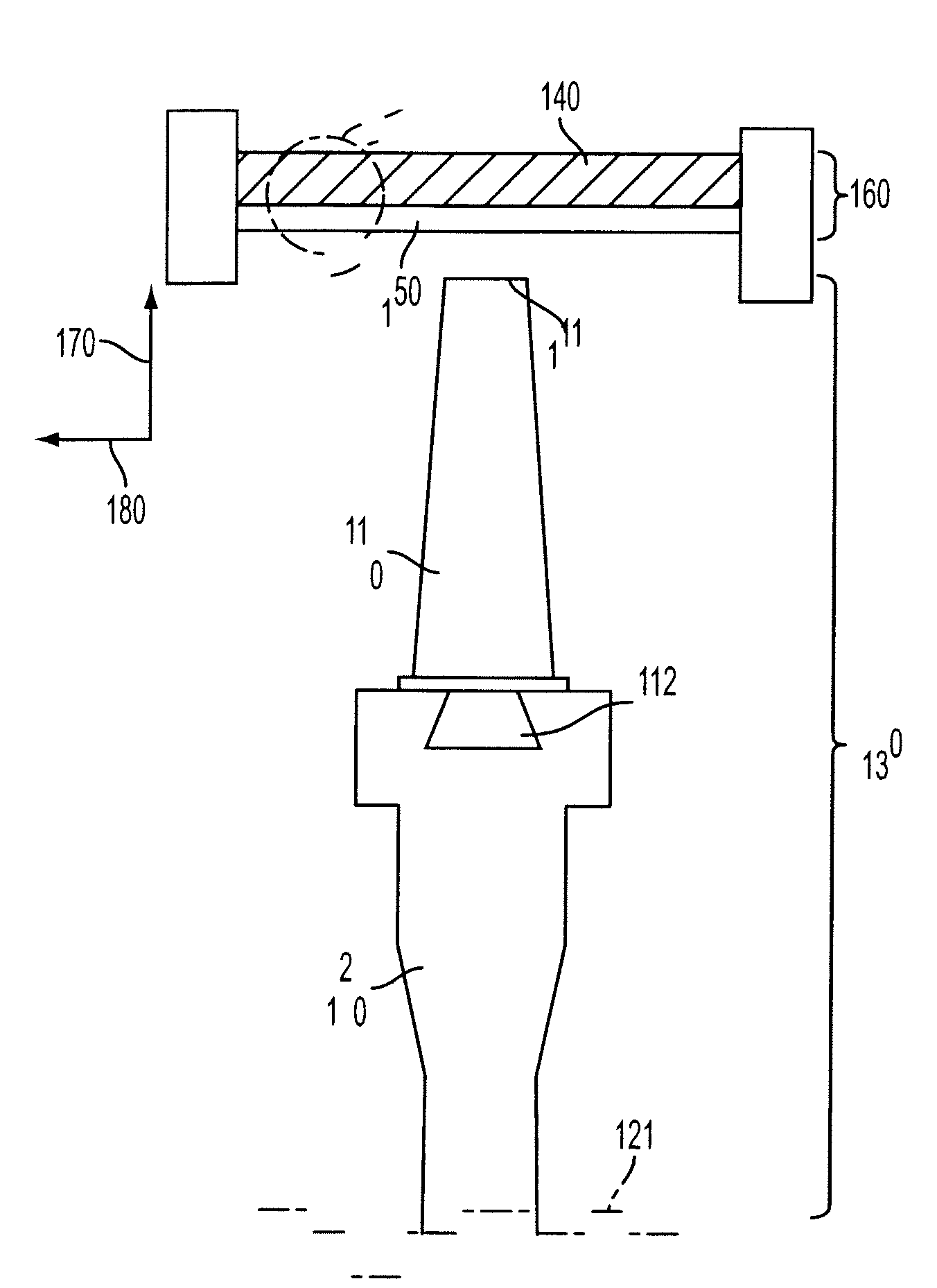
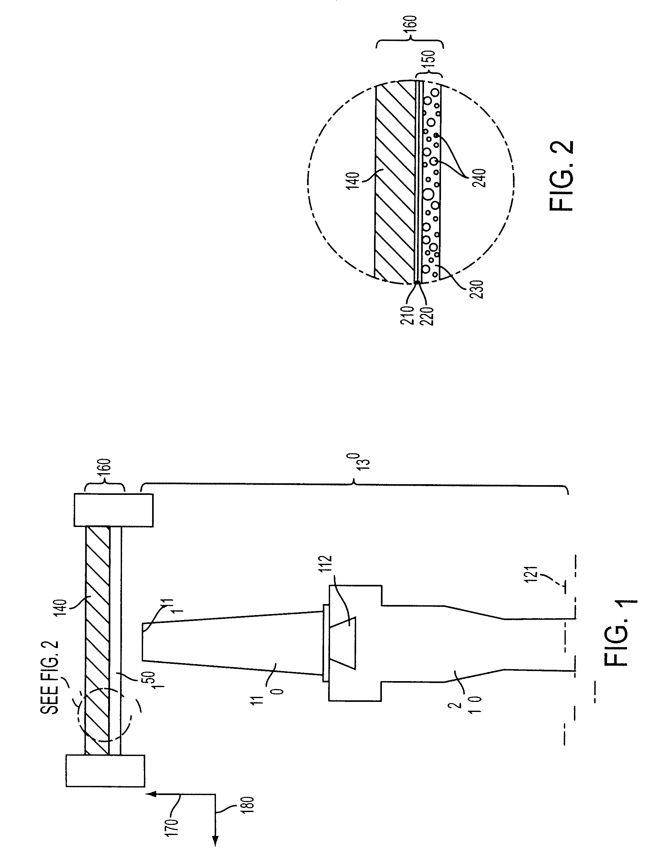
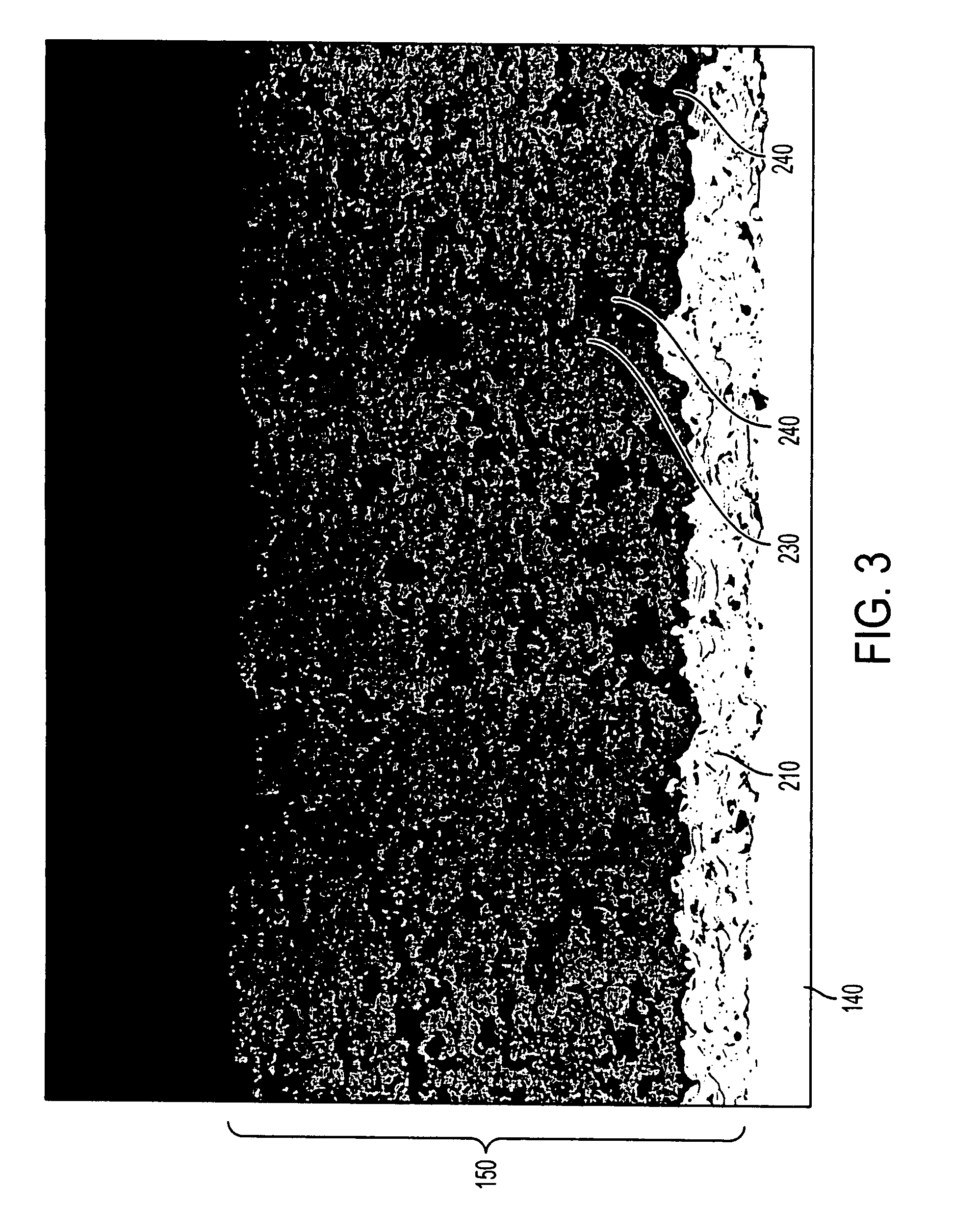
[0032]FIG. 1 illustrates a cross-sectional view of a stage of a turbine engine consisting of a rotor 130 and a static shroud or casing 160. FIG. 1 shows a blade 110 that, through its blade root 112, is affixed to a rotating disc 120 that rotates around an axis 121. Hot gases passing over the blade 110 in the direction 180 impart rotational movement to the blade / disc assembly. The blade has a tip 111 that may be bare or carry an abrasive on it. The blade 110 and the disc 120 form the rotor part of the turbine engine stage that rotates around the axis 121. FIG. 1 also shows a casing 160 which acts to house the pressurized turbine stage and guides the gases to flow over the turbine blade 120 in a direction 180 or parallel to the casing wall 160. The casing wall 160 consists of a casing metal construction 140, which may be provi...


PUM

PropertyMeasurementUnit
Temperatureaaaaaaaaaa
Sizeaaaaaaaaaa
Sizeaaaaaaaaaa

Abstract

Ceramic abradable materials, in particular thermally sprayable ceramic abradable powder materials, and abradable seals formed by thermally spraying the materials include dysprosia (Dy2O3) and zirconia (ZrO2). Coatings are porous whereby the porosity, in part, is induced by plastic or fugitive phases. Abradable seal coatings comprising dysprosia and zirconia exhibit improved thermal shock and sintering resistance and can be worn into tolerance by untreated, bare turbine blades, at least in certain regimes of relative blade speed and coating porosity. Ceramic abradable seal coatings comprising dysprosia and zirconia can be used up to 1200° C.

Description

CROSS REFERENCE TO RELATED APPLICATIONS[0001]This application claims priority under 35 U.S.C. § 119(e) from U.S. Provisional Patent Application No. 60 / 811,799, filed on Jun. 8, 2006, which is incorporated herein in its entirety by reference.STATEMENT REGARDING SPONSORED RESEARCH OR DEVELOPMENT[0002]Not Applicable.REFERENCE TO SEQUENCE LISTING[0003]Not Applicable.BACKGROUND OF THE INVENTION[0004]1. Field of the Invention[0005]The invention relates generally to the field of clearance control or abradable materials. More particularly, the invention relates to a ceramic abradable material and, even more particularly, to a ceramic abradable coating that includes dysprosia and zirconia where the dysprosia serves the purpose of a stabilizer and also imparts a dramatic improvement in thermal shock resistance and abradability to the abradable coating compared to prior art abradable coatings.[0006]2. Description of Related Art[0007]In an aircraft or stationary gas turbine engine there is a ho...

Claims


Application Information

Patent Timeline
IPC IPC(8): C23C4/10C09D1/00C08K3/10B32B5/16
CPCC04B35/48Y10T428/2982C04B38/067C04B2111/00146C04B2111/00982C04B2111/2084C23C4/105F01D5/005F01D5/288F01D11/122Y02T50/67Y02T50/672C04B35/488F05D2300/134F05D2300/2118F05D2230/80F05D2230/312F05D2230/313F05D2230/311F05D2230/90F05D2300/15C04B38/0074C23C4/11Y02T50/60
Inventor SPORER, DIETER R.TAECK, ULRIKEDORFMAN, MITCHELL R.NICOLL, ANDREW R.GIANNOZZI, MASSIMOGIOVANNETTI, IACOPO
Owner SULZER METCO (US) INC
Learn More