

System and Method For Standoff Detection of Human Carried Explosives
a technology of human-to-human interaction and detection method, which is applied in the field of systems and methods for remotely detecting human-to-human-to-human-to-human-to-human-to-human-to-human-to-human-to-human-to-human-to-human-to-human-to-human-to-human-to-human-to-human-to-human-to-human-to-human-to-human-to-human-to-human interaction,
- Summary
- Abstract
- Description
- Claims
- Application Information
AI Technical Summary
Benefits of technology
Problems solved by technology
Method used
Image

Examples
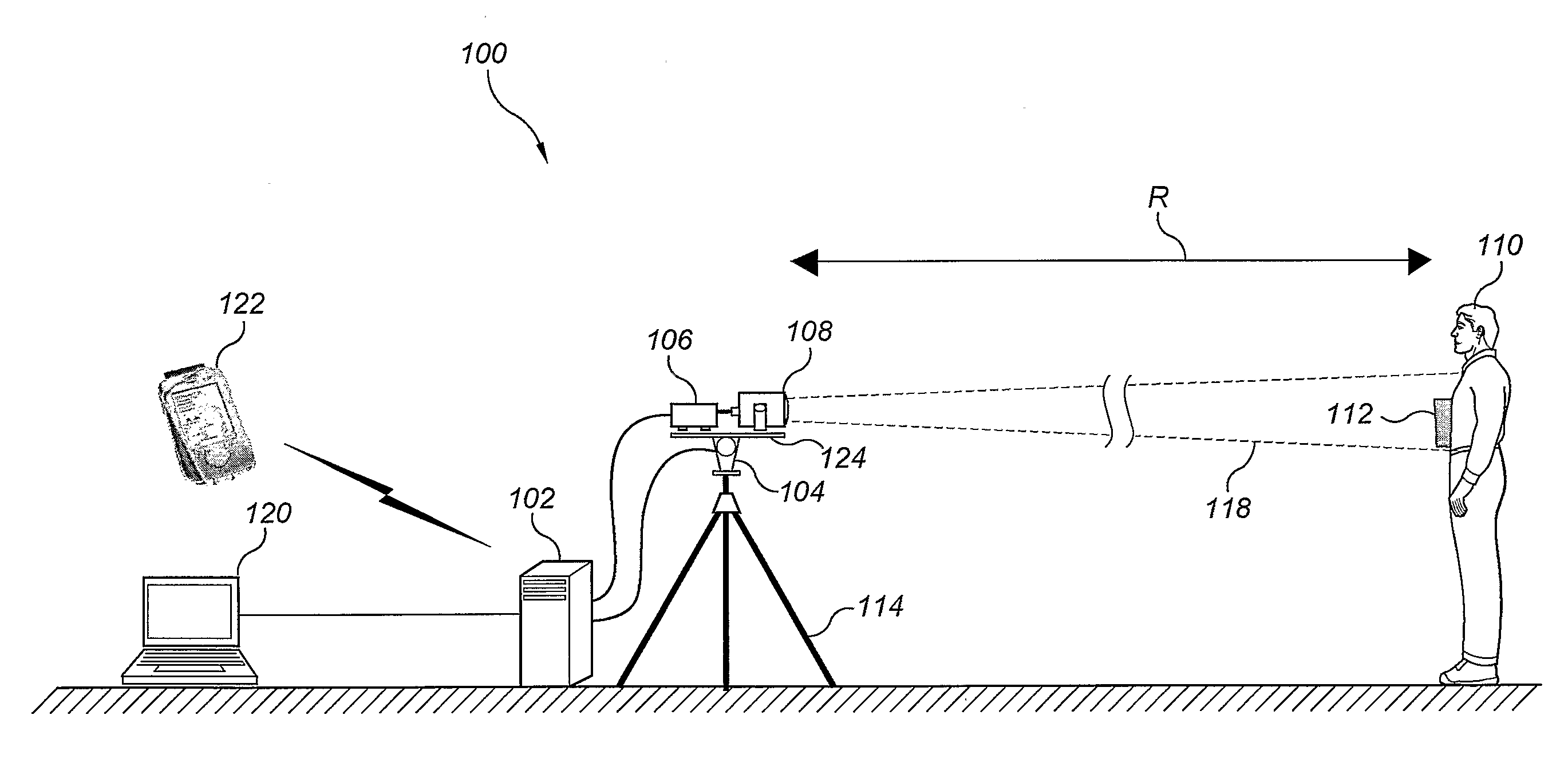
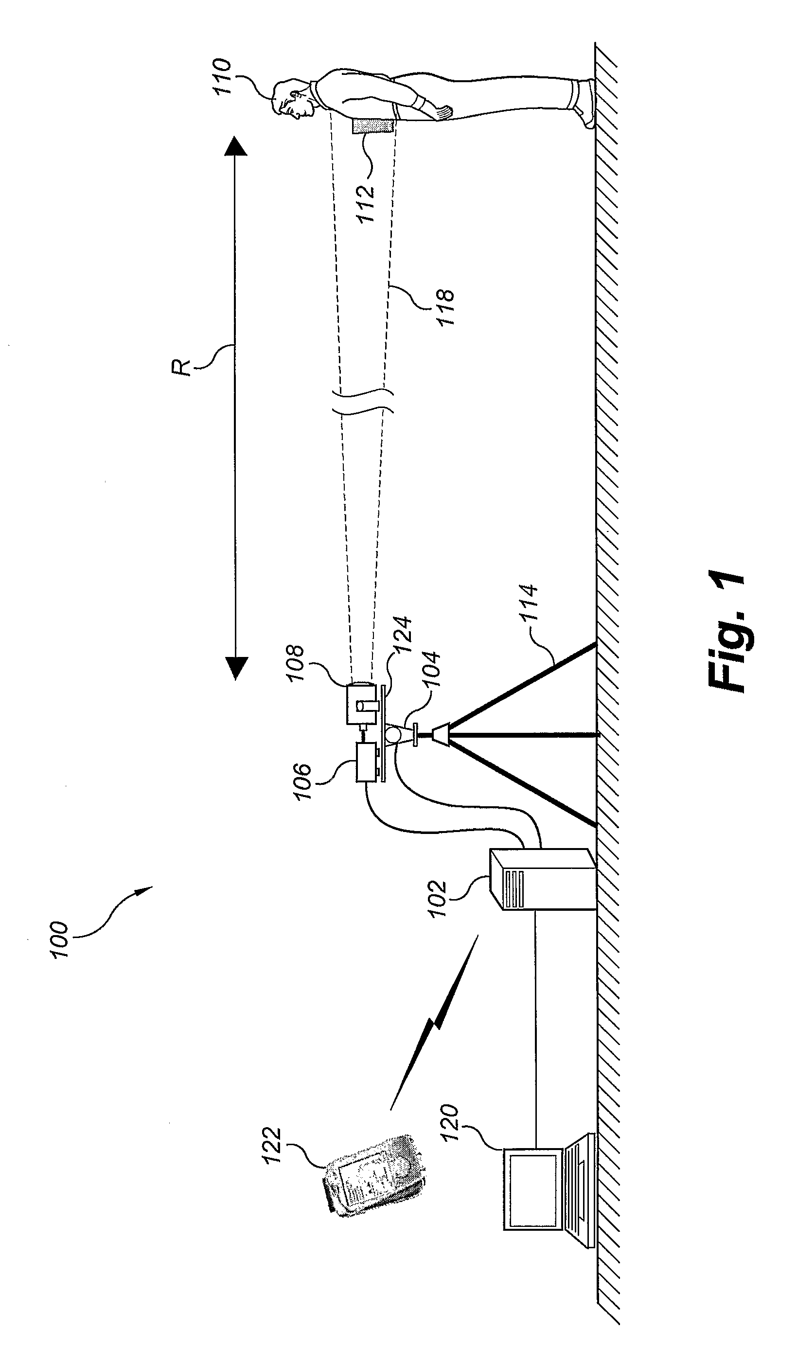
embodiment 100
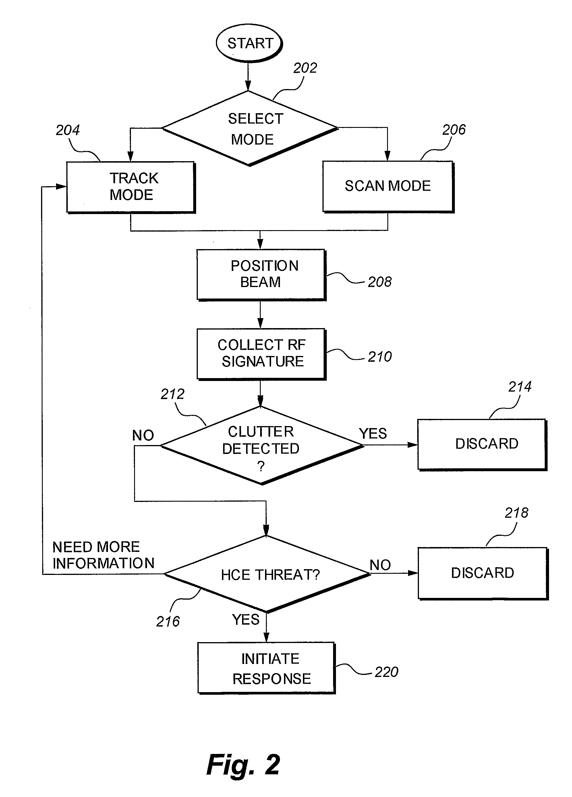
[0068]Events that trigger a “threat” determination may then be used to initiate one or more mitigation responses 220 to be discussed later. Information available at the output of the radar-only embodiment 100 of the invention includes the estimated range and heading of the threat relative to the radar sensor, as well as the time at which the threat was detected. Additional characteristics, such as velocity vector, radar cross-section and other distinguishing signature features might also be provided to the operator as an aid to intercepting the threat 112. As an example, one may consider continuing the radar track during the interception operation to provide real-time updates of position and heading information on detected threats 112.
[0069]The preferred embodiment incorporates a radar system having at least one transmit polarization and at least one receive polarization, i.e., at least a dual polarized system. However, in alternative embodiments the radar system may be alternately ...
embodiment 300
[0074]As previously disclosed, in the radar plus video embodiment 300, video signals from the WFOV video camera 306 are operated upon by a video-tracking algorithm stored in program memory that is designed to detect and extract moving subjects from the WFOV camera 306 field of regard 308. The heading of each detected moving subject is estimated, and corresponding pan / tilt position commands are sent to the gimbal 104. Also at this time, the processor 302 sends a trigger to the radar transceiver 106 to initiate the transmission of one or more RF signals through the antenna 108 toward the subject 110 and any threat device 112 present on the subject 110. Energy scattered off of the device 112 and subject 110 is collected at the antenna 108 and forwarded to the transceiver 106, which then transmits the data to the processor 302 where the data is processed using signal detection and classification algorithms.
[0075]The signal detection and classification algorithms classify the reflected r...
PUM
 Abstract
Description
Claims
Application Information