Adaptive antenna matching for portable radio operating at VHF with single-chip based implementation

a portable radio and adaptive antenna technology, applied in the field of wireless communication, can solve the problems of inability to achieve, variation in return loss, significant loss of sensitivity, etc., and achieve the effect of maximizing one or more performance criteria of the radio

Inactive Publication Date: 2008-06-05
TEXAS INSTR INC
View PDF34 Cites 63 Cited by
  • Summary
  • Abstract
  • Description
  • Claims
  • Application Information

AI Technical Summary

Benefits of technology

[0016]There is also provided in accordance with the invention, an adaptive antenna matching circuit for use in a single-chip radio comprising a first varactor coupled from a first terminal to ground, the first terminal coupled to an antenna, a second varactor coupled from a second terminal to ground, the second terminal forming an output of the circuit, an inductor coupled across the first terminal and the second terminal and adaptation means for determining optimum values of the first varactor and the second varactor that maximize one or more performance criteria of the radio.
[0017]There is further provided in accordance with the invention, an adaptive antenna matching circuit for use in an on-chip radio comprising a first varactor coupled from a first pin to ground, the first pin coupled to an external antenna, a second varactor coupled from a second pin to ground, the second pin adapted to provide an output of th...

Problems solved by technology

The low VSWR implies the existence of a high mismatch loss between the antenna and the radio which results in a significant loss of sensitivity of as low as −30 dB with an average loss of approximately −8 dB.
Variations in antenna impedance results in variations in return loss due to close proximity of the antenna to the hand or body in the case of a chip antenna.
This cannot be achieved, however, due to the almost −30 dB of miss match loss.
The antenna impe...

Method used


Image

  • Adaptive antenna matching for portable radio operating at VHF with single-chip based implementation
  • Adaptive antenna matching for portable radio operating at VHF with single-chip based implementation
  • Adaptive antenna matching for portable radio operating at VHF with single-chip based implementation

Examples


first embodiment

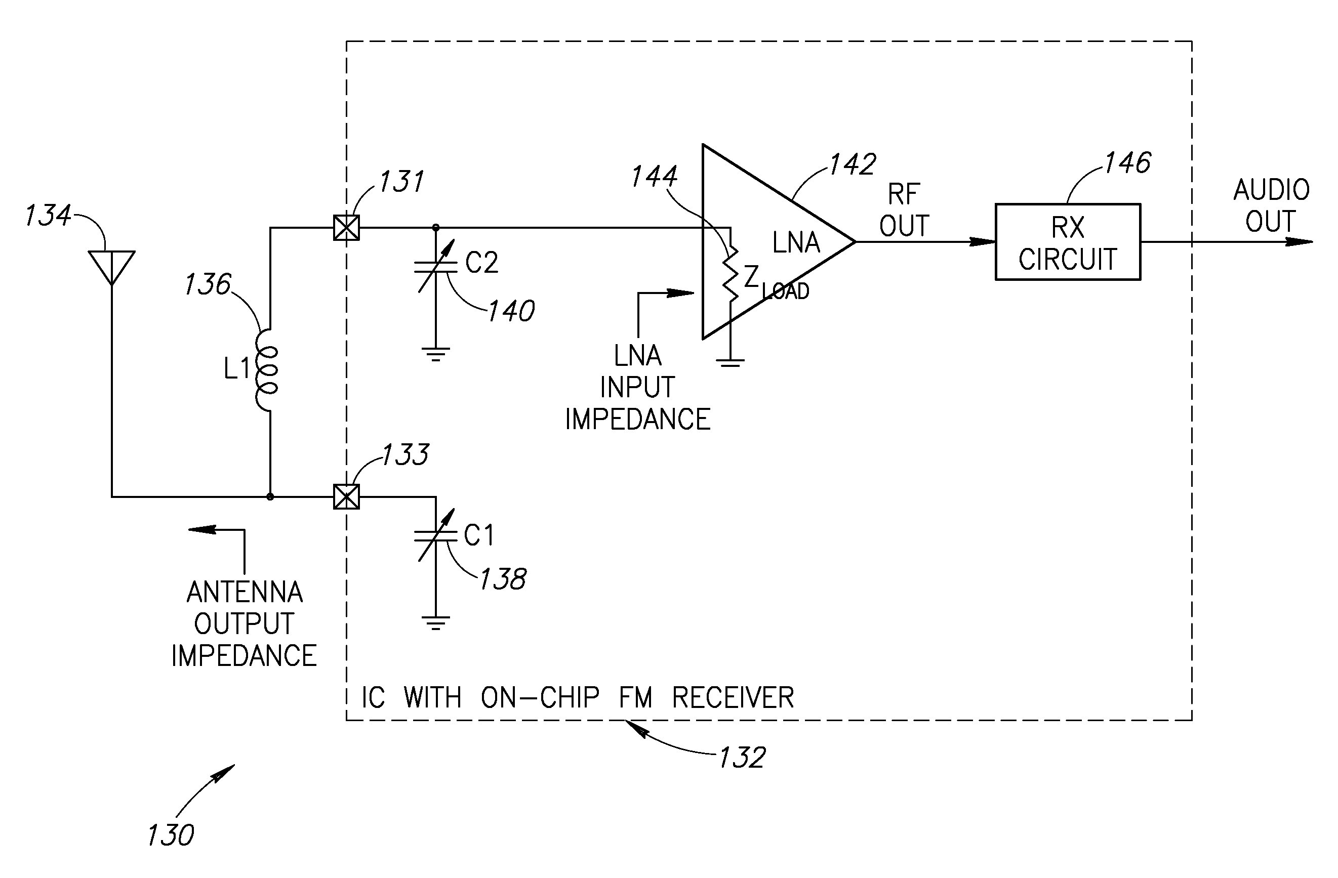
[0044]A block diagram illustrating a first embodiment single chip VHF radio receiver incorporating the adaptive antenna matching circuit of the present invention is shown in FIG. 7. The radio receiver, generally referenced 130, comprises an IC with on-chip VHF radio (i.e. FM radio) receiver 132, external inductor L1136 and antenna 134. The on-chip FM radio circuit 132 comprises variable capacitor (i.e. varactor) C1138 coupled to pin (terminal) 133 which is also coupled to antenna 134, varactor C2140 coupled to pin (terminal) 131, low noise amplifier (LNA) 142 with load impedance 144 and receiver circuit 146 which functions to generate the output audio output signal. Indictor L1136 is coupled across pins (terminals) 131, 133. Note that the dashed line represents the chip boundary wherein L1 and the antenna are off-chip and the rest of the circuit is on-chip. Note that all embodiments of the invention contemplate an adaptive matching network where any or all of the varactors and induc...

second embodiment

[0048]A block diagram illustrating a second embodiment single chip VHF radio receiver incorporating the adaptive antenna matching circuit of the present invention is shown in FIG. 8. The radio receiver, generally referenced 150, comprises an IC with on-chip VHF radio (i.e. FM radio) receiver 152, external inductor L1160 and antenna 154. The on-chip FM radio circuit 152 comprises variable capacitor (i.e. varactor) C1158 coupled to pin (terminal) 162 which is also coupled to antenna 154, varactor C2170 coupled to pin (terminal) 166, capacitor C3168, low noise amplifier (LNA) 172 with load impedance 174 and receiver circuit 173 which functions to generate the audio output signal. Indictor L1160 is coupled across pins (terminals) 162, 166. Also shown are ESD diodes D1156, D2164 coupled to pins 162, 166 respectively. The ESD diodes (i.e. diacs or back to back zener diode equivalents) protect the chip circuitry from high voltage static discharge which would likely destroy the circuitry if...

third embodiment

[0051]A block diagram illustrating a third embodiment single chip VHF radio receiver incorporating the adaptive antenna matching circuit of the present invention is shown in FIG. 9. Without the loss of generality, the algorithm and examples presented herein are applied to VHF-FM modulated signals. The mechanism described herein, however, may be applied to any other modulation scheme without departing from the spirit and scope of the invention. The radio receiver, generally referenced 180, comprises an on-chip radio receiver circuit 182, external inductor L1186 and antenna 184. The radio receiver circuit 182 comprises varactors C1188, C2190, VHF LNA 192, local oscillator (LO) 193, I path mixer 194, baseband amplifier and filter 198, analog to digital converter (ADC) 202, Q path mixer 196, baseband amplifier and filter 200, analog to digital converter (ADC) 204, FM detector 206, stereo decoder 208 with pilot phase locked loop (PLL) 210, received signal strength indication (RSSI) measu...


PUM


Abstract

A novel and useful apparatus for and method of improving antenna matching and reducing mismatch loss for a VHF receiver such as an FM receiver. The invention can be used in a very low cost implementation of a single chip radio such as used in cellphone applications. The impedance of the low cost VHF antenna in cellphone application can dramatically vary across time, frequency and depending on the human body proximity resulting in a large mismatch loss. The adaptive antenna matching mechanism uses dynamically configurable on-chip variable capacitors to provide a custom matching network with the external inductor in a pi-network configuration. The variable ranges of the on-chip capacitors enable adaptation in a closed loop manner so that the optimum SNR is achieved thus ensuring minimum mismatch loss. The mechanism measures RSSI and SNR and, using a novel adaptive calibration mechanism, adjusts the internal matching network capacitors such that the mismatch loss is minimized.

Description

REFERENCE TO PRIORITY APPLICATION[0001]This application claims priority to U.S. Provisional Application No. 60 / 868,239, filed Dec. 1, 2006, entitled “Adaptive Antenna Matching for Portable Radio Operating At VHF With Single-Chip Based Implementation”, incorporated herein by reference in its entirety.FIELD OF THE INVENTION[0002]The present invention relates to the field of wireless communications and more particularly relates to an apparatus for and method of adaptive antenna matching for portable radio operating at VHF (e.g., FM receiver) with single chip based implementation.BACKGROUND OF THE INVENTION[0003]Wire antennas are in widespread use in wireless communications operating in high frequency (HF) and very high frequency (VHF) bands (i.e. 50 to 100 MHz) to receive broadcast signals such as commercial broadcast FM. The wired stereo headphones that are normally used with audio devices, such as radios and multimedia devices, to listen to audio serve a secondary purpose of function...

Claims


Application Information

Patent Timeline
IPC IPC(8): H01Q1/50H01Q1/24
CPCH03D3/007H04B1/18H03J2200/06H03H7/40H04B17/21
Inventor TSFATI, YOSSIBURRA, GANGADHARSILVERSTEIN, BRUCE
Owner TEXAS INSTR INC
Why Eureka
Try Eureka