Method for Deployment of a Medical Device

a medical device and deployment method technology, applied in the field of cardiac arrest devices, can solve the problems of difficult to achieve average flow, and achieve the effects of reducing radial and bending load, reducing friction, and reducing the generation of particulates

Inactive Publication Date: 2008-06-05
MEDICAL VALUE PARTNERS
View PDF1 Cites 246 Cited by
  • Summary
  • Abstract
  • Description
  • Claims
  • Application Information

AI Technical Summary

Benefits of technology

[0061]b. Reduces the radial and bending load on the distal bearing since in the illustrative embodiment, the distal bearing is only required to hold the casing stationary.
[0068]b. In the absence of axial forces, the drive cable / drive shaft is free to “float” within the sheath, thereby minimizing contact pressure, friction, and particulate generation.
[0069]Regarding point C—the elimination of the axial forces on the central drive cable—a relatively more flexible assembly can therefore be employed. This flexibility simplifies the process of negotiating the vascular system to deploy the pump assembly within a cardiac patient. It is notable that the drive cable does not experience axial forces during insertion and deployment, operation, or withdrawal.
[0070]Regarding point D, the stationary distal support of the illustrative embodiment is better able to bear the bending loads of the casing than the rotating distal support of that is disclosed in the '855 patent. Furthermore, the distal support of the illustrative embodiment is the full diameter of the impeller hub, which enhances stability.

Problems solved by technology

Historically, it has been difficult to achieve average flows greater than about 2 to 2.5 liters per minute against physiologic pressures through a 12-French catheter, which has a diameter of 4 millimeters.

Method used


Image

  • Method for Deployment of a Medical Device
  • Method for Deployment of a Medical Device
  • Method for Deployment of a Medical Device

Examples


Embodiment Construction

[0081]The following terms are defined for use in this Specification, including the appended claims:[0082]Distal means relatively further from a first end of a torque transmission line that connects a motor to a pump assembly in cardiac-assist device 110. The motor is located at the first (proximal) end of the torque transmission line.[0083]Proximal means relatively closer to the first end of the torque transmission line.[0084]Proximate means “near to.”[0085]Axial means an axis or direction that is coincident with a centerline (of a device) and contrary to “radial.”[0086]Operatively coupled means that the operation of one device affects another device. For example, if a drive cable is “operatively coupled” to an impeller, it is capable of driving the impeller (i.e., causing the impeller to rotate). Operatively coupled devices need not be directly physically coupled.

Other definitions may be provided later in this disclosure.

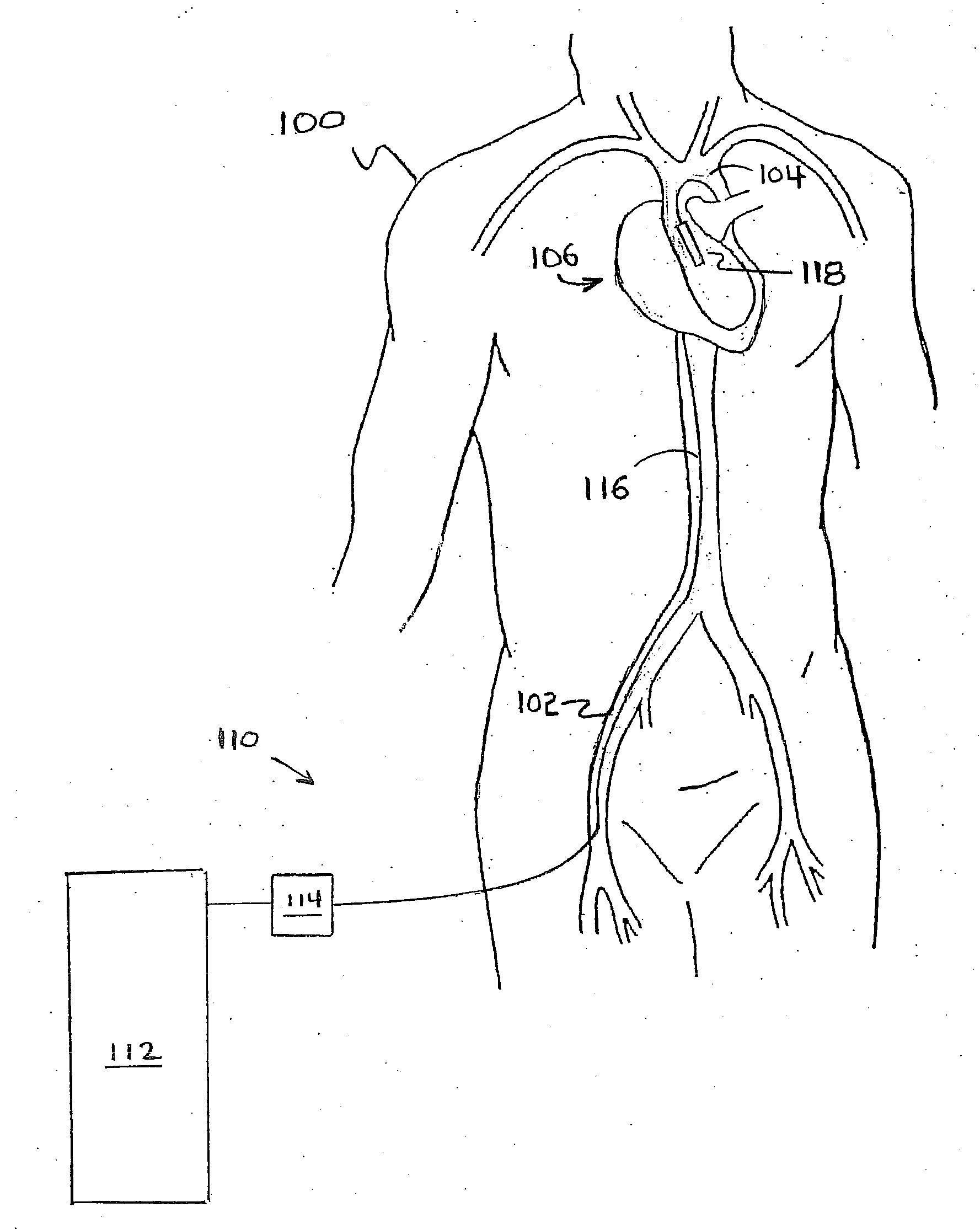
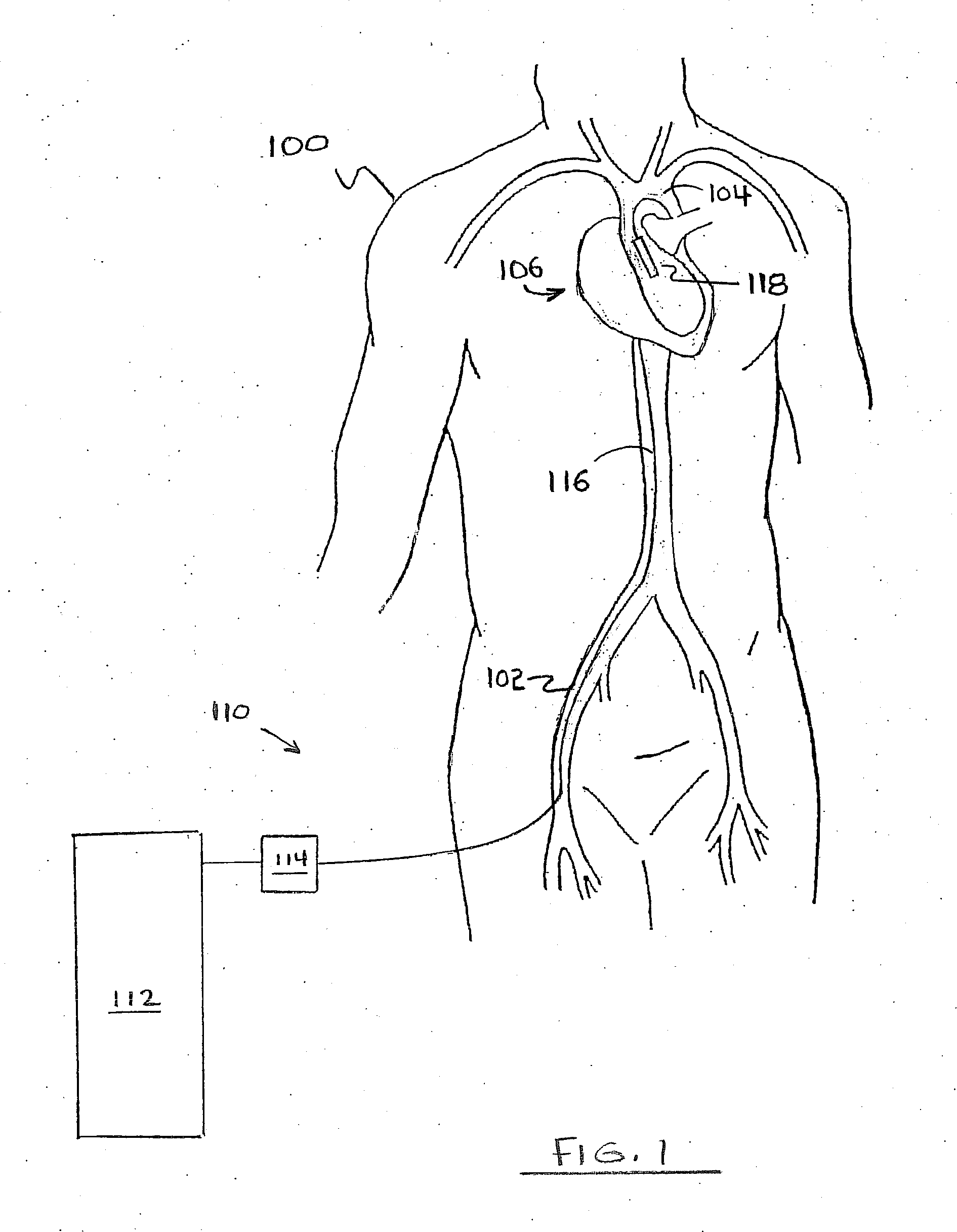
[0087]FIG. 1 depicts a silhouette of human torso 100. Heart 1...


PUM


Abstract

A method for deploying a cardiac-assist device is disclosed. In accordance with the illustrative embodiment, an introducing tube, such as a catheter, sheath, or the like is inserted into the vascular system and advanced beyond the aortic arch. The cardiac-assist device is then inserted into the tube, advanced through it, and deployed from its distal end. In some embodiments, the diameter of the cardiac-assist device expands when it deploys from the distal end of the tube.

Description

FIELD OF THE INVENTION[0001]The present invention relates to cardiac-assist devices in general, and, more particularly, to blood pumps suitable for percutaneous insertion into the vascular system.BACKGROUND OF THE INVENTION[0002]Acute heart failure is the sudden inability of the heart to fill with or pump a sufficient volume of blood. The afflicted patient may become weak and short of breath and, in some instances, die. In the most severe acute heart failure episodes, the patient may suffer from cardiogenic shock, a condition that is associated with high reported mortality rates.[0003]Acute heart failure occurs in a variety of contexts. For example, some patients who are hospitalized for Acute Coronary Syndrome (i.e., heart attack and unstable angina) develop acute heart failure. Furthermore, some open-heart surgery patients develop acute heart failure. Acute heart failure also complicates certain illnesses. Additionally, some patients who undergo a Percutaneous Coronary Interventio...

Claims


Application Information

Patent Timeline
Patent Type & Authority Applications(United States)
IPC IPC(8): A61M1/12A61M60/17A61M60/232A61M60/414A61M60/585A61M60/865
CPCA61M1/101A61M1/125A61M1/1034A61M1/1024A61M60/414A61M60/148A61M60/865A61M60/232A61M60/585A61M60/17
Inventor SHIFFLETTE, J. MICHAEL
Owner MEDICAL VALUE PARTNERS
Why Eureka
Try Eureka