Systems and Arrangements for Clock and Data Recovery in Communications

Active Publication Date: 2008-06-12
GLOBALFOUNDRIES US INC
View PDF14 Cites 23 Cited by
  • Summary
  • Abstract
  • Description
  • Claims
  • Application Information

AI Technical Summary

Benefits of technology

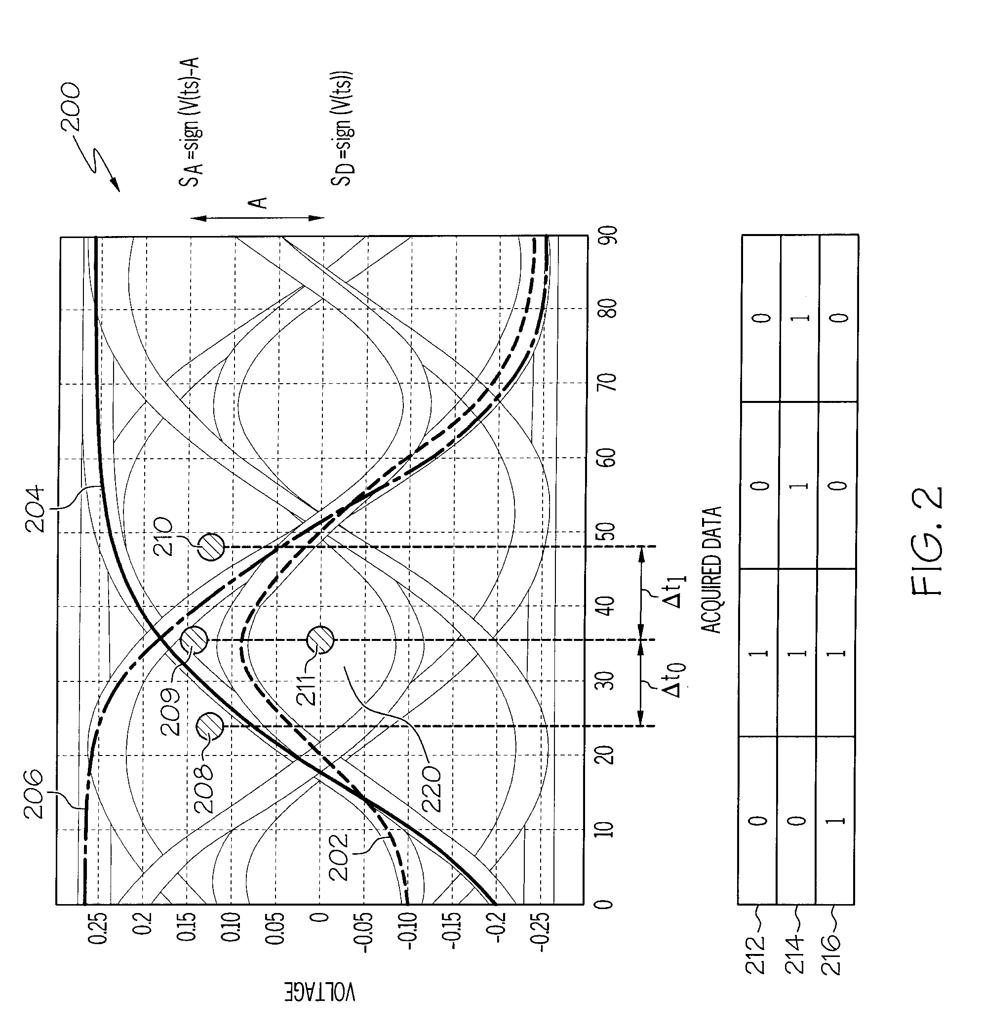
[0016]In a specific embodiment, time-amplitude samples can be taken over the course of hundreds of bits, tagged with bit patters and stored such that the time-amplitude samples can be related to the bit pattern occurring during their acquisition. When specific bit patterns, such as five large three bit transitions occurring at various times are all identified, the time-amplitude samples related to all five occurrences of the large transitions can all be retrieved for analysis. Such a robust data set on waveforms that are relatively steady over time allows the logic module to compare time-amplitude samples that are taken at many different time locations for the same bit pattern to determine where the rising edge or falling edge is occurring (on the average). Also such a data set can provide medians and averages that can be utilized to improve the data sampling and waveform sampling process.
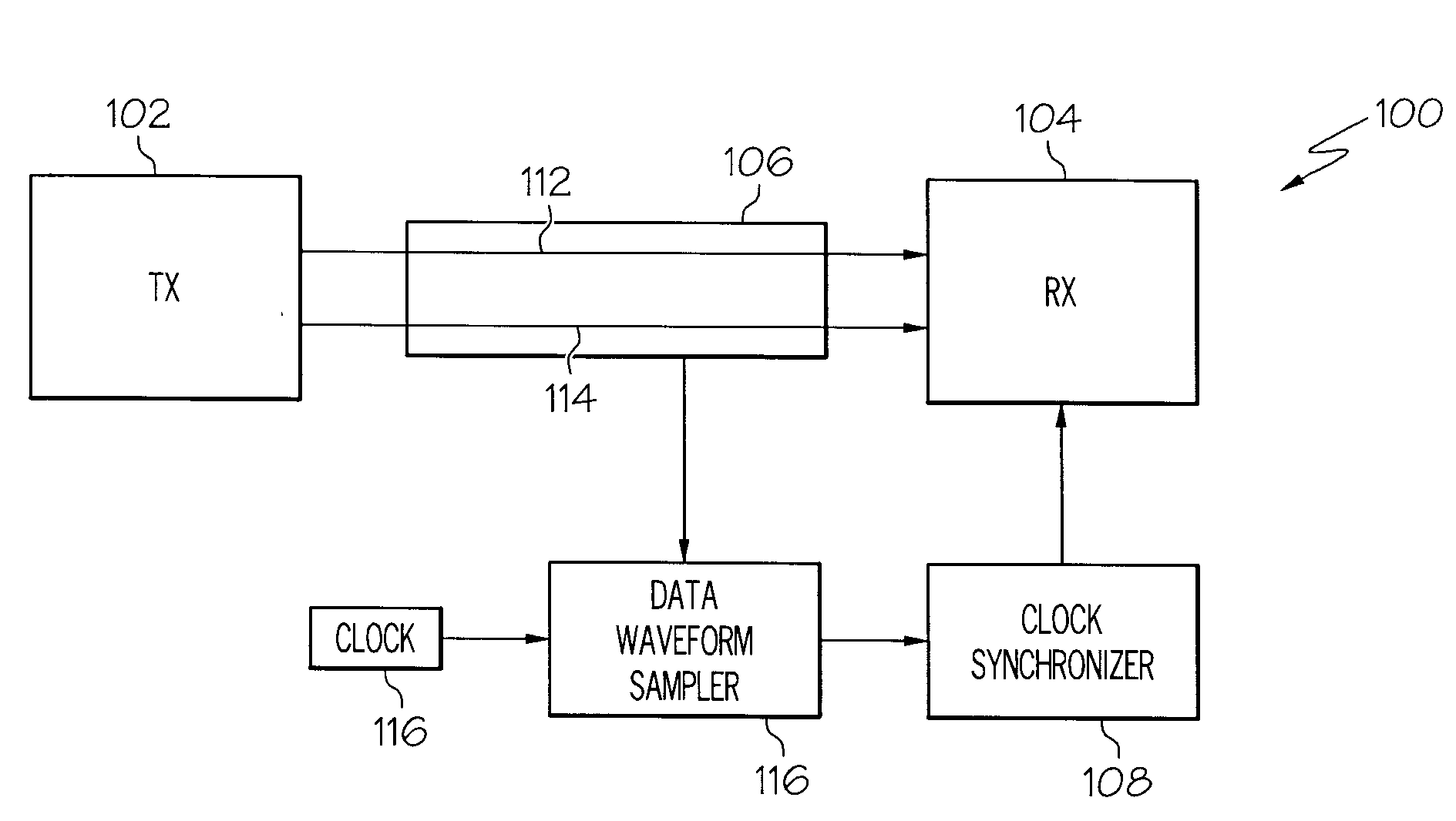
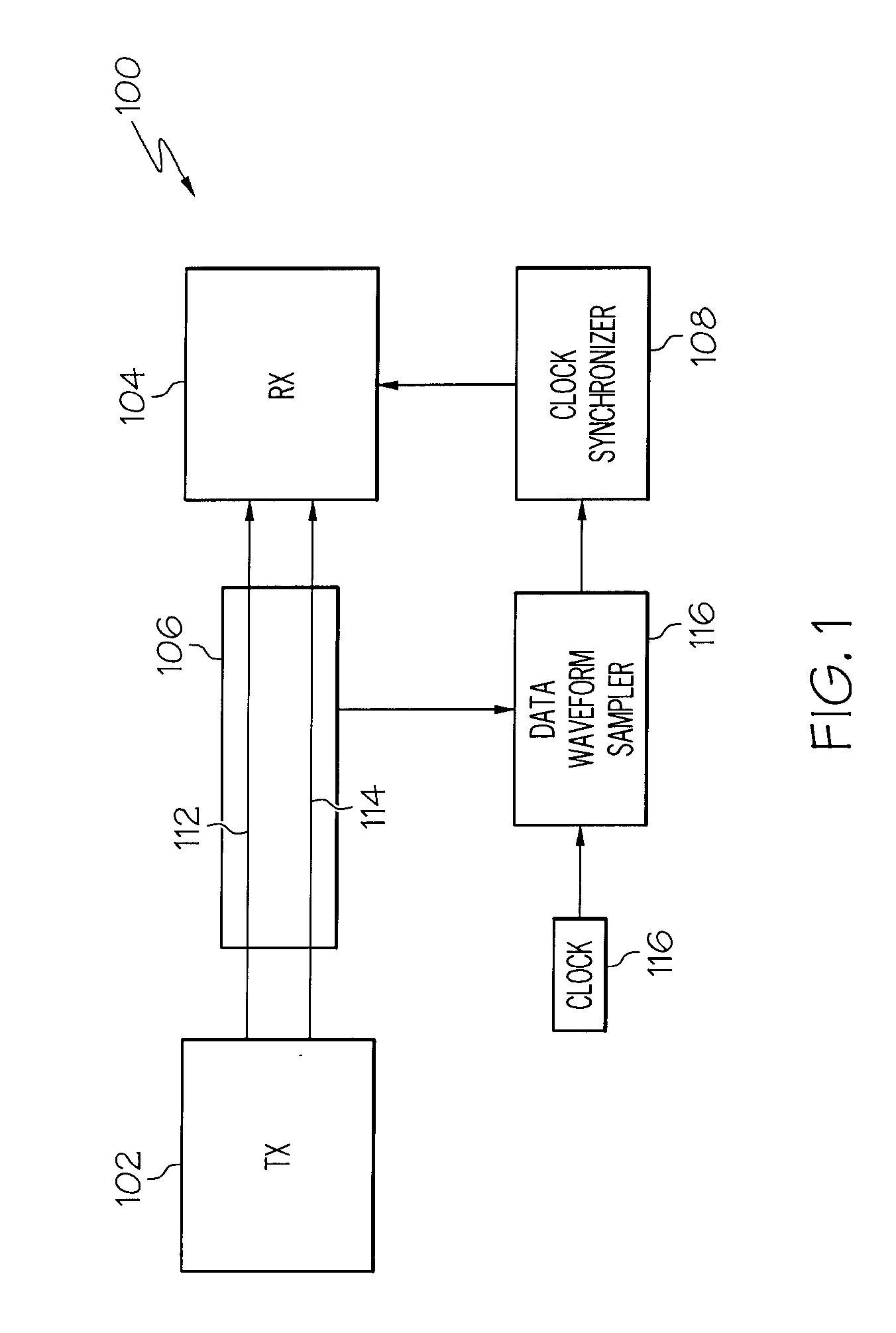
[0017]In another embodiment, a communication system is provided that has a transmitter to transmit a data waveform, a transmission line to convey the data wavefo

Problems solved by technology

Traditional CDR systems utilize two system clocks or two sampling clock signals that cycle every bit interval or bit cycle and thus consume considerable power.
Although the frequency of the sampling clock can be set based on the frequency of the transmitter clock, unknown delays can occur between the transmitter and the receiver.
In addition, the timing of the received waveform can undergo random changes, known as timing jitter, which are induced by non-idealities of the clock circuitries.
However, it is often difficult to determine an optimum time to sample the data waveform because for example, the optimum time may not be at the center of the eye pattern due to waveform anomalies.
As stated above, virtually all of these designs have multiple system clocks and other control circuitry and such systems draw a significant amount of power and take

Method used


Image

  • Systems and Arrangements for Clock and Data Recovery in Communications
  • Systems and Arrangements for Clock and Data Recovery in Communications
  • Systems and Arrangements for Clock and Data Recovery in Communications

Examples


Embodiment Construction

[0026]The following is a detailed description of embodiments of the disclosure depicted in the accompanying drawings. The embodiments are in such detail as to clearly communicate the disclosure. However, the amount of detail offered is not intended to limit the anticipated variations of embodiments; on the contrary, the intention is to cover all modifications, equivalents, and alternatives falling within the spirit and scope of the present disclosure as defined by the appended claims. The descriptions below are designed to make such embodiments obvious to a person of ordinary skill in the art.

[0027]While specific embodiments will be described below with reference to particular configurations of hardware and / or software, those of skill in the art will realize that embodiments of the present invention may advantageously be implemented with other equivalent hardware and / or software systems. Aspects of the disclosure described herein may be stored or distributed on computer-readable med...


PUM


Abstract

A sampling clock signal controller for receivers of digital data is disclosed. Specific bit patterns of a data waveform can be identified, and stored time samples of the waveform that correspond to the specific bit patterns can be analyzed to improve the timing of a sampling clock signal. These “time-amplitude” samples on known bit patterns can be utilized to determine if a sample on the data waveform should be taken before the center of the eye pattern, at the center of the eye pattern, or after the center of the eye pattern and by what time change. Accordingly, a single low power clock can be utilized to adjust the timing of the sample clock such that improved communication scan be achieved. Such a single clock system has reduced power requirements and increased accuracy.

Description

FIELD OF INVENTION[0001]The present disclosure is in the field of communications systems and more particularly in the field of clock and data recovery systems.BACKGROUND[0002]Communication systems typically utilize some form of clock system to synchronize communications between a transmitter and a receiver. In digital communication systems the receiver must operate at the same average frequency as the transmitting end to prevent loss of information. When digital signals are transported over a network of digital communication links, switching nodes, multiplexers, transmission line interfaces, and the task of keeping all the entities operating at the same average frequency is referred to as network synchronization.[0003]Generally, in Gigahertz communication systems it is important that a receiver reads or samples the data waveform when the amplitude of the data waveform reaches a steady state. Many techniques can be utilized to determine when to sample the data waveform and this proce...

Claims


Application Information

Patent Timeline
IPC IPC(8): H04L7/00H03K3/017
CPCH04L7/0004H04L7/042H04L7/0334
Inventor CRANFORD, HAYDEN C.FRIEDMAN, DANIEL J.MEGHELLI, MOUNIRTOIFL, THOMAS H.
Owner GLOBALFOUNDRIES US INC
Why Eureka
Try Eureka