Plural bore to single bore ion transfer tube

a technology of ion transfer tube and single bore, which is applied in the direction of electric discharge tube, particle separator tube, isotope separation, etc., can solve the problems of reducing the efficiency of heat transfer to the ion/gas flow, the maximum temperature at which the tube may be operated is limited, and the interface cannot be easily integrated with a conventional skimmer structure having a single aperture, etc., to achieve high ion/gas flow rate

Active Publication Date: 2008-06-19
THERMO FINNIGAN
View PDF10 Cites 44 Cited by
  • Summary
  • Abstract
  • Description
  • Claims
  • Application Information

AI Technical Summary

Benefits of technology

[0011]By dividing the ion flow among a plurality of channels in the first segment of the ion transfer tube, high ion / gas flow rates may be obtained without having a substantial adverse effect on heat transfer efficiency and consequent desolvation, thereby allowing relatively large numbers of ions to be delivered to a downstream mass analyzer. Further, by combining the ion / gas flow in a common channel in the second segment of the ion transfer tube, a single gas stream expansion is generated, which may be interfaced with a single aperture in a plate, or a skimmer structure.

Problems solved by technology

However, increasing the cross-sectional area through which the ions and gas are transported has a detrimental effect on the efficiency of heat transfer to the ion / gas flow.
Of course, the heat transfer to the ion / gas flow may be increased by raising the tube wall temperature, but the maximum temperature at which the tube may be operated will be limited by material considerations, as well as the tendency of certain analyte molecules to undergo thermal dissociation.
However, the ion / gas flows emerge from the exit ends of the capillaries as a geometrically complex set of multiple expansions, which (although suitable for use with the ion funnel) could not be easily interfaced to a conventional skimmer structure having a single aperture.
Also in this case, the multichannel plate could not be easily interfaced with a conventional skimmer structure having a single aperture.

Method used


Image

  • Plural bore to single bore ion transfer tube
  • Plural bore to single bore ion transfer tube
  • Plural bore to single bore ion transfer tube

Examples


Embodiment Construction

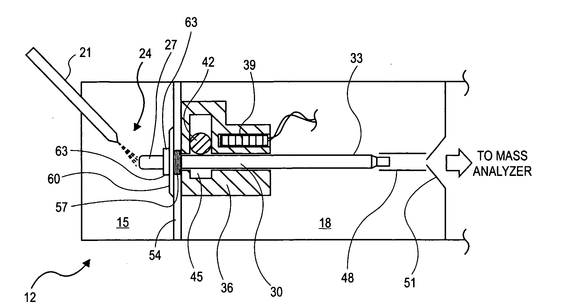
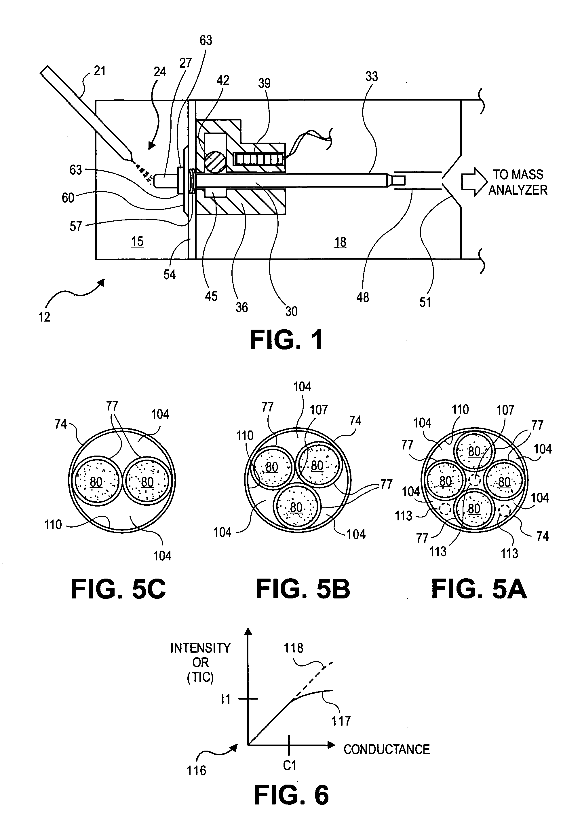
[0020]FIG. 1 shows a diagrammatic and partial sectional view of an ion source 12 of a mass spectrometer. The ion source 12 includes a first chamber 15 and a second chamber 18, maintained at a lower pressure than the first chamber 15 during operation. For example and without limitation, the first chamber may be generally at atmospheric pressure while the second chamber may be at a pressure on the order of one Torr. The ion source system 12 includes a spray probe 21 supported in the first chamber in a position that directs a spray 24 of droplets of sample solution including an analyte and a solvent from a tip of the spray probe into an inlet end 27 of an ion transfer tube 30. The spray probe 21 may be an electrospray probe, in which the sample solution is directed through a spray needle maintained at an elevated potential relative to other surfaces of the first chamber 15 so as to produce a spray of electrically charged droplets, or may alternatively take the form of an atmospheric pr...


PUM


Abstract

An ion source includes an ion transfer tube having two segments for transporting a sample fluid containing ions between a first chamber and a second chamber maintained at a reduced pressure relative to the first chamber. A first segment may include a plurality of channels and heat conductive walls forming the plurality of channels. The plurality of channels and walls forming the channels promote efficient convective heat transfer to the sample fluid, thereby enabling operation at relatively high sample fluid flow rates, resulting in an increase in the number of ions that may be delivered to a mass analyzer. A second segment forms a single common channel that receives a plurality of sample streams and enables them to combine into a single ion stream that may be introduced as a single gas stream expansion into the second chamber.

Description

BACKGROUND OF THE INVENTION[0001]1. Field of the Invention[0002]This invention generally relates to an ion source for a mass spectrometer, and more specifically to an ion transfer tube for transporting ions between regions of different pressure in a mass spectrometer.[0003]2. Description of Related Art[0004]Ion transfer tubes, also referred to as capillaries, are well-known in the mass spectrometry art for transporting ions from a spray chamber, which typically operates at or near atmospheric pressure, to a region of reduced pressure. Generally described, an ion transfer tube typically consists of a narrow elongated conduit having an inlet end open to the spray chamber, and an outlet end open to the reduced-pressure region. Ions formed in the spray chamber (e.g., via an electrospray ionization (ESI) or atmospheric pressure chemical ionization (APCI) process), together with partially desolvated droplets and background gas, enter the inlet end of the ion transfer tube, traverse its le...

Claims


Application Information

Patent Timeline
Patent Type & Authority Applications(United States)
IPC IPC(8): H01J49/26
CPCH01J49/0404B01D59/44H01J49/00H01J49/062
Inventor ATHERTON, PAUL R.DUNYACH, JEAN JACQUESSPLENDORE, MAURIZIOWOUTERS, ELOY R.
Owner THERMO FINNIGAN
Why Eureka
Try Eureka