[0007]There is, therefore, a need for the ability to efficiently collect the light from multiple LEDs, generating light with other wavelength converting material physically far away from the LED chips and to construct a light system with higher light brightness compared to an individual LED.
[0009]In an embodiment of the present invention, an LED based illumination system with enhanced brightness includes a
light source such as LEDs, light couplers for efficiently collecting and collimating the light from LEDs, wavelength selective filters, light concentrators that focus the
collimated light, a cavity constructed by
layers of wavelength converting material such as phosphorescent materials located the focus planes of the light concentrators. The LEDs provide the light of a first wavelength (the term “wavelength” is used in this disclosure for convenience, but it should be understood to refer to a
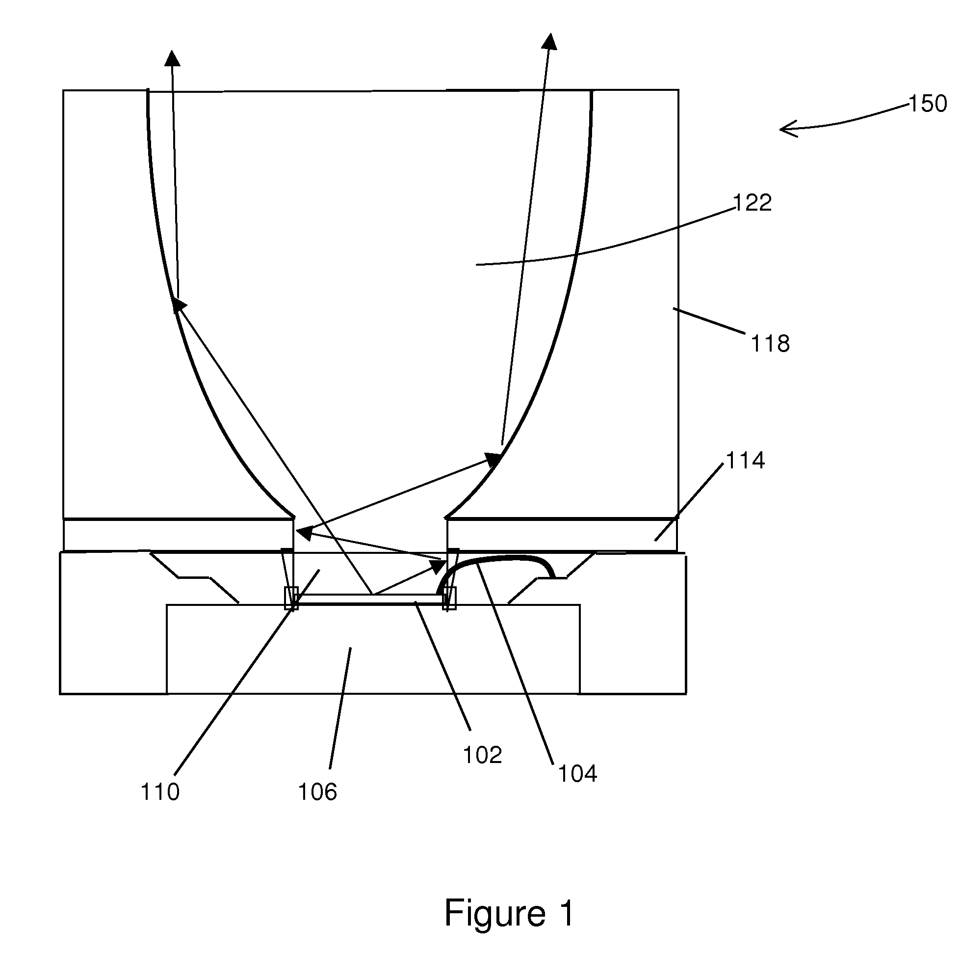
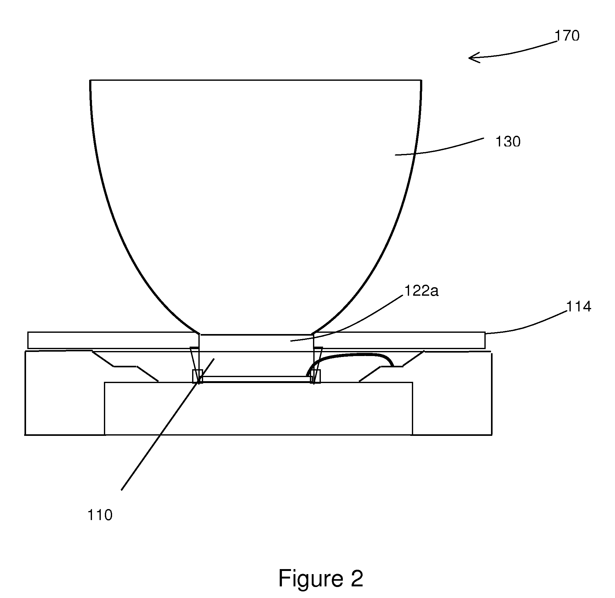
wavelength range unless otherwise clear from the context). The light couplers efficiently collect and collimate the light from the LED. Each coupler includes a light tunnel portion and a compound parabolic reflecting surface portion. Exiting LED light that is substantially perpendicular to the LED
chip surface is directly applied to the compound
parabolic reflector and is collimated. The LED light that is substantially parallel to LED chip surface strikes the light tunnel portion and is guided into the parabolic reflecting portion through one or multiple reflections and is also collimated. A wavelength
selective filter is placed at the output of the collimated light of the first wavelength but before the light
concentrator that focus the collimated light. At the focus of the
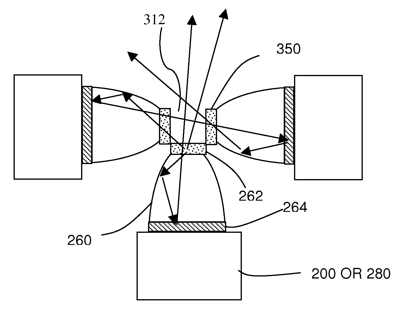
concentrator is the layer of the cavity made of a
wavelength conversion material. The layer of the
wavelength conversion material forms a cavity that passes the focused light of the first wavelength. There is at least one aperture on the cavity to allow light at both the first wavelength and a second wavelength pass. The light at the first wavelength passing through the filters interacts with the wavelength converting material and generates the light of the second wavelength that is different from the first wavelength. The wavelength selective filters reflect the light with the second wavelength and prevent the light with second wavelength from going back to the light couplers and then back to the
light source such as LEDs. Therefore the light of the second wavelength can only propagate in the forward direction and is trapped and cycles inside the cavity until it exits the cavity through an aperture on the cavity. Since the side surfaces of the cavity are form from the focus surface and the aperture is significantly smaller than 50% of total cavity area, the brightness of the output light is enhanced.
[0010]In another embodiment of the present invention, an LED based illumination system with enhanced brightness includes a cavity constructed by a layer of wavelength converting material such as phosphorescent material, light concentrators that focus the collimated LED light, wavelength selective filters, and optical fibers or
fiber bundles that transport the collimated light from LEDs, and light couplers for efficiently collecting and collimating light from LEDs. The light couplers efficiently collect and collimate the light of the first wavelength from the LED. Each coupler provides a light tunnel portion and a compound parabolic reflecting surface portion. Exiting LED light that is substantially perpendicular to the LED chip surface is directly applied to the compound
parabolic reflector and is collimated. LED light that is substantially parallel to the LED chip surface strikes the light tunnel portion and is guided into the parabolic reflecting portion through one or multiple reflections and is also collimated. The collimated light of the first wavelength is then collected by an
optical fiber. LED output from multiple fibers can be further combined through
fiber bundling or
fiber fusion. A wavelength
selective filter is placed at the fiber output of the collimated light of first wavelength but before the light
concentrator that focus the collimated light. At the focus of the concentrator is the layer of the cavity made of the wavelength conversion material. The light of the first wavelength passes through and interacts with the wavelength converting material that generates light of a second wavelength different from the first wavelength. The light of the second wavelength that travels back to the concentrator will be reflected back by the wavelength selective filters which prevent the light of the second wavelength from going back to the fiber and then back to the LED. Further improvement of brightness is obtained from the increase of the effective
light conversion efficiency since the loss of light that go back to the light source is prevented, as well as the reduction of beam spot size by the concentrator. The light of the second wavelength from the light conversion material can only propagate in the forward direction as the collimated light of the first wavelength. The light of the second wavelength can directly exit the cavity or cycle inside the cavity until exiting the cavity through an aperture on the cavity. When the
reflectivity of optical components is high enough (or the loss is low), there is no significant light loss. With an appropriate size of the aperture, the output light brightness is enhanced.

