Method For Reducing Nitrogen Oxide Emissions of a Bubbling Fluidized Bed Boiler and an Air Distribution System of a Bubbling Fluidized Bed Boiler

a technology of bubbling fluidized bed and boiler, which is applied in the direction of combustion types, lighting and heating apparatus, combustion processes, etc., can solve the problems of increasing the amount of flue gas in the boiler, the method is not efficient enough for getting nitrogen oxide, and the fuel is almost impossible to create fuel combustion conditions. to achieve the effect of reducing nitrogen oxide emissions

Inactive Publication Date: 2008-06-26
METSO POWER OY
View PDF3 Cites 10 Cited by
  • Summary
  • Abstract
  • Description
  • Claims
  • Application Information

AI Technical Summary

Benefits of technology

[0011]The purpose of the present invention is to provide a method for reducing nitrogen oxide emissions of a bubbling fluidized bed boiler burning biofuel, by means of which the above-mentioned drawbacks can be avoided. In addition, the purpose of the invention is to create an air distribution system of a bubbling fluidized bed boiler.

Problems solved by technology

Still problematic are the fine and light fuels, because most of the fuel particles do not end up in the fluidized bed, but they are pulled with the fluidizing gas and secondary air to the upper parts of the furnace.
Thus, it is almost impossible for the fuels to create fuel combustion conditions in the furnace that are controlled and favourable to reducing nitrogen oxides.
However, this method is not efficient enough for getting the nitrogen oxide emissions of the boiler in accordance with the strict emission standards.
The problem with this solution is that it causes the amount of flue gases in the boiler to increase, in which case the size of the furnace must be increased, which in turn raises the price of the boiler.
With wet fuels the amount of heat needed for drying reduces the combustion temperature in the secondary stage too much, thus preventing the creation of conditions favourable for reducing the nitrogen oxides.

Method used


Image

  • Method For Reducing Nitrogen Oxide Emissions of a Bubbling Fluidized Bed Boiler and an Air Distribution System of a Bubbling Fluidized Bed Boiler
  • Method For Reducing Nitrogen Oxide Emissions of a Bubbling Fluidized Bed Boiler and an Air Distribution System of a Bubbling Fluidized Bed Boiler
  • Method For Reducing Nitrogen Oxide Emissions of a Bubbling Fluidized Bed Boiler and an Air Distribution System of a Bubbling Fluidized Bed Boiler

Examples


Embodiment Construction

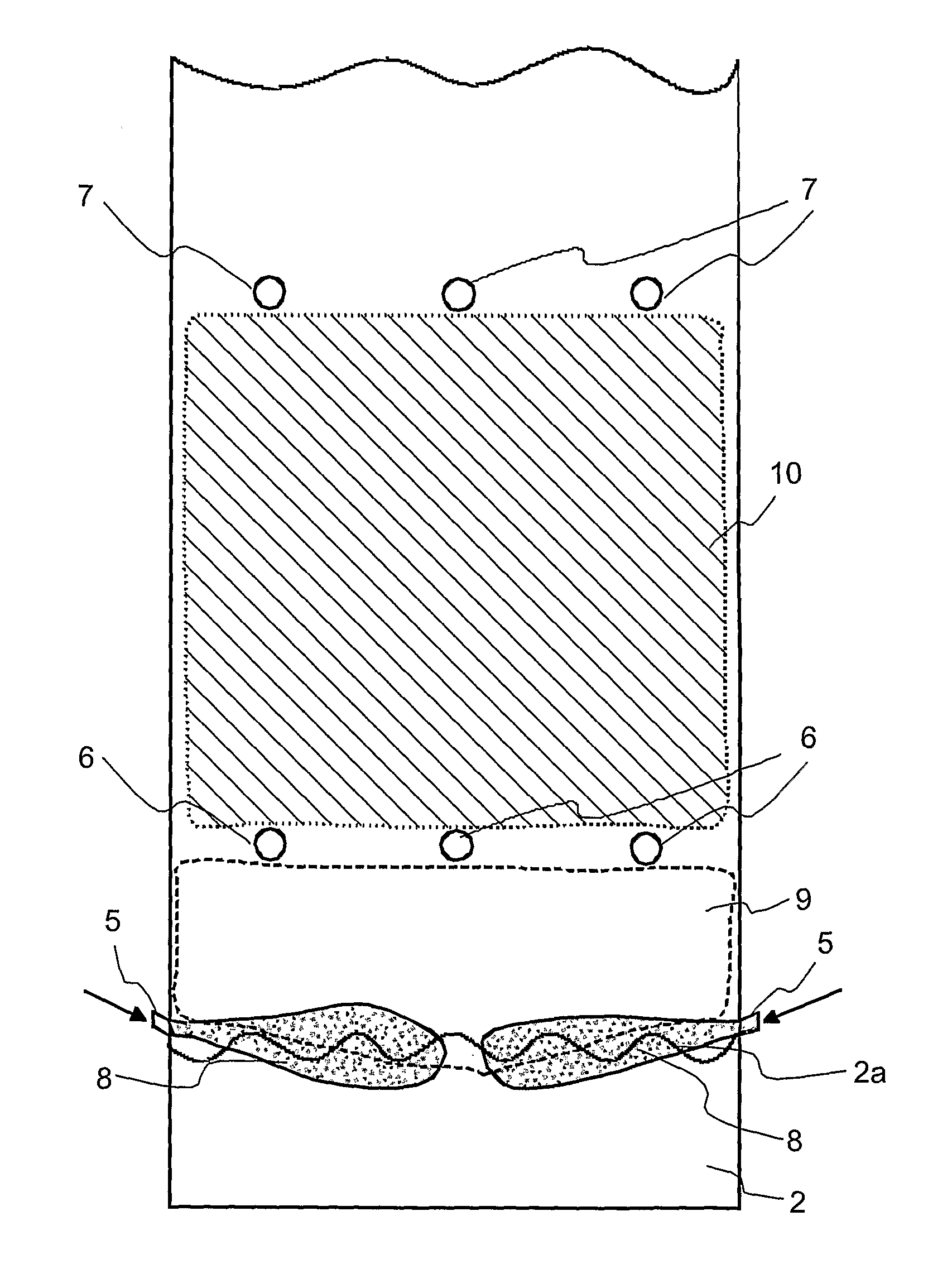
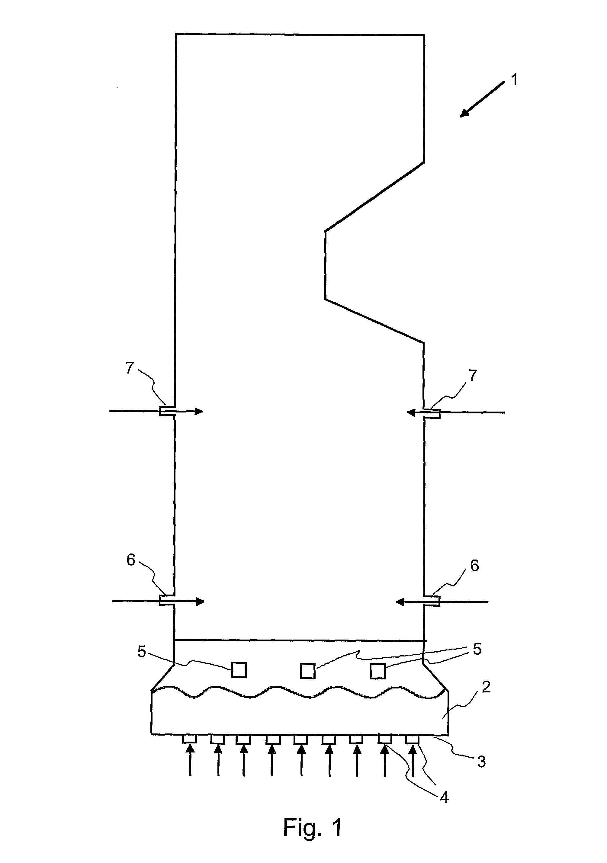
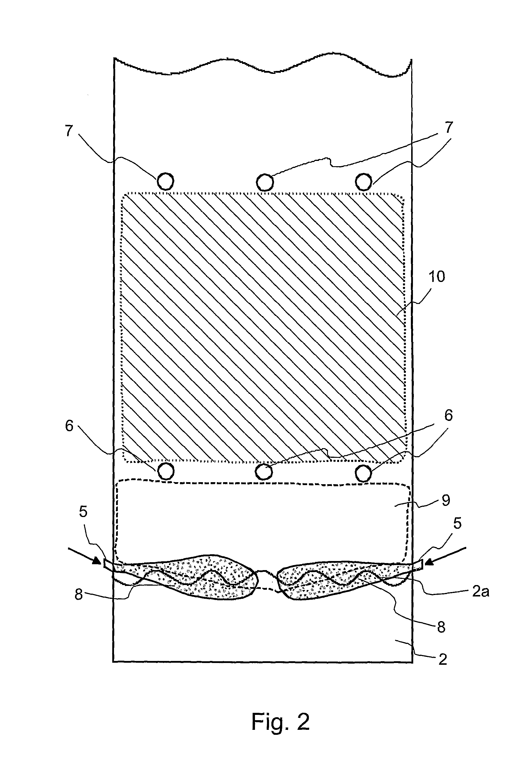
[0032]FIG. 1 shows a side view of a furnace of a bubbling fluidized bed boiler 1. There is a fluidized bed 2 composed of bed material on the bottom of the furnace. Fluidizing gas is supplied to the furnace 1 through nozzles 4 arranged on its bottom 3, which gas fluidizes the bed material. The fluidizing gas can be solely air, or it may be a mixture of air and recirculating gas. The fuel is supplied to the fluidized bed 2 from fuel supply means 5 arranged above the surface of the fluidized bed and placed substantially on a mutually same level. In the figure there are three fuel feeding means, but their number may vary depending on the size of the furnace or other parameters of the boiler. Fuel feeding means can also be arranged on the opposite side wall (not shown) of the furnace substantially on the same level with the fuel feeding means arranged on the side wall, as shown in the figure. They can also be placed on the front and / or back walls of the furnace. The fuel is fed to the fl...


PUM


Abstract

A method for reducing nitrogen oxide emissions of a bubbling fluidized bed boiler burning biofuel and an air distribution system for a bubbling fluidized bed boiler biofuel. A fluidized bed is arranged in a lower part of a furnace of the boiler. The bed is fluidized by fluidizing gas that includes primary air. Fuel is fed to the fluidized bed, which dries and pyrolizes into pyrolysis gas including volatile matter of the fuel. The gas rises upwards in the furnace and burns. Secondary air is supplied above the fluidized bed from secondary air nozzles, and tertiary air is supplied above the secondary air nozzles. A part of primary air is supplied in connection with fuel feeding such that the fuel is forced substantially on the surface of the fluidized bed, thus pyrolizing entirely, and at least a part of the pyrolysis gases formed in the pyrolysis is burned by primary air such that the air coefficient in relation to the volatile matter of fuel in the pyrolysis gases is in the substoichiometric area.

Description

FIELD OF THE INVENTION[0001]The invention relates to a method for reducing nitrogen oxide emissions of a bubbling fluidized bed boiler burning biofuel according to the preamble of the appended claim 1. The invention also relates to an air distribution system of a biofuel-burning bubbling fluidized bed boiler in accordance with the preamble of the appended claim 13.[0002]In this description biofuel refers to solid fuels, wherein the portion of volatile matter in ash-free dry solids is over 60%. This type of fuels are, for example, peat, bark, wood chips, sawdust, waste construction timber, sludge created in process industry, and municipal solid waste.BACKGROUND OF THE INVENTION[0003]Bubbling fluidized bed boilers are generally used in energy production, wherein the fuels include biofuels, such as, for example, peat and wood chips. In the lower part of the furnace of a bubbling fluidized bed boiler there is a fluidized bed, which is composed of a fine, incombustible material, typicall...

Claims


Application Information

Patent Timeline
Patent Type & Authority Applications(United States)
IPC IPC(8): F23G7/00F23C10/22F23CF23G5/30F23G7/10
CPCF23C10/00F23G7/10F23G5/30F23C2201/101
Inventor DERNJATIN, PAULIFABRITIUS, MARKOROPPANEN, JUKKA
Owner METSO POWER OY
Why Eureka
Try Eureka