Laser scanner

a laser scanner and laser technology, applied in the field of laser scanners, can solve the problems of high production cost, functional interference with the laser radar device, disadvantages of the state of the art, etc., and achieve the effect of improving the temperature compensation of the avalanche photodiode, reducing the adverse effects of external light, and not reducing the operating speed of the laser scanner

Inactive Publication Date: 2008-06-26
SICK AG
View PDF7 Cites 14 Cited by
  • Summary
  • Abstract
  • Description
  • Claims
  • Application Information

AI Technical Summary

Benefits of technology

[0009]An advantage of the invention is that the detection sensitivity for the receipt of the light signal can be set in dependence on the light intensity of the light receiving arrangement for the light measuring signals. The reflection measurement made with the light measuring signal permits an adjustment of the actual detection sensitivity of the light receiving arrangement so that the amount of light from the light signal reflected by the object lies in the optimal operating range of the light receiving arrangement. This provides an additional measurement system and permits one to generate a reflection characteristic prediction for the light pulse without reducing the operating speed of the laser scanner.
[0010]An electronic signal processor which preferably follows the light receiving arrangement is used to preset the detection sensitivity of the light receiving arrangement for the next light pulse in dependency on the remission signal of the light measuring signal. In a preferred embodiment of the invention, the detection sensitivity for the light pulse is set by appropriately varying a switching threshold and / or an amplification factor in the electric evaluation unit associated with the light receiving arrangement that receives the light pulse. Such an adaptation of the detection sensitivity of the laser scanner to the anticipated reflection values renders the laser scanner much less susceptible to interferences which can be caused, for example, by exterior light sources.
[0011]The light receiving arrangement is configured to adjust the amplification of the received light pulse by an avalanche photodiode in dependency on the remission signal. This advantageous embodiment of the present invention sets the avalanche photodiode voltage in the light receiving arrangement as a function of the actual or measured light measuring signal. Aside from reducing the potential adverse effects external light can have on the laser scanner, this also provides an improved temperature compensation for the avalanche photodiode. In addition, for high reflectivities, this improves the measurement accuracy because the downstream electronic evaluation unit is less likely to be overcompensated.
[0012]The light measuring signal has a relatively lesser strength and advantageously is significantly smaller than the strength of the light pulses and, in the preferred form, the strength of the light measuring signals is about 1% of that of the light pulses. Objects to be detected can have differing reflection characteristics. Very bright and in particular mirrored surfaces have a very high reflectivity, and very dark objects have a lesser reflectivity, which, at a minimum, may be approximately 1.8% according to applicable guidelines. When a light pulse strikes an object, the electronics should not be overcompensated because this would lead to wrong measurements. For such cases, it is advantageous that the light measuring signal has such a small strength. A further advantage is that even when measuring the reflectivity of the object with the light measuring signal, no overcompensation will be encountered. Reliable conclusions can therefore be drawn concerning the reflection characteristics of the object.
[0013]In a further embodiment of the invention, the light source is formed by the pulsed laser. Thus, no additional light source is needed because the pulsed laser can perform the functions of the light source. The light source therefore illuminates the to-be-detected object with a light that has the same optical spectrum for measuring the reflection characteristics of the object and illuminating the object with the light pulse. By using the pulsed laser for measuring the reflectivity as well as detecting the object, another electronic unit for controlling an additional light source is not needed. Systemic errors are also reduced by using only one pulsed laser.
[0014]In addition, only the pulsed laser must be precisely aligned. The need for aligning an additional light source is eliminated.

Problems solved by technology

This state of the art is disadvantageous when the laser radar device monitors a large region where objects with widely differing reflection characteristics must be detected.
High signal dynamics entail high production costs and can functionally interfere with the laser radar device.
Since the detection sensitivity of the light receiving arrangement must be set for the lowest expected signal strength generated by dark objects in the monitored region, such external light sources can significantly interfere with the proper functioning of the light receiving arrangement because the external light generates significant background noise which is superimposed onto the actual measurement signal.
The resulting received signals generate saturation effects and / or background noise influences which significantly compromise the accuracy of the distance measurement.
It is also known to repeat incorrect measurements by changing the detection sensitivity of the light receiving arrangement.
Such techniques cannot be used with laser radar devices that change the direction of the light because the beam direction of two or more successive light pulses are changed to such a degree that different objects or object segments are struck by them which cannot be related to each other.
This can be reduced by correspondingly reducing the changes in the light directions, but this is not practically possible because the reaction time of the laser radar device would thereby be correspondingly reduced.

Method used


Image

  • Laser scanner
  • Laser scanner
  • Laser scanner

Examples


Embodiment Construction

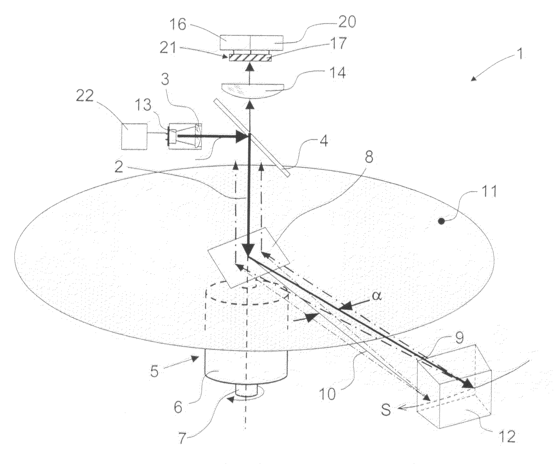
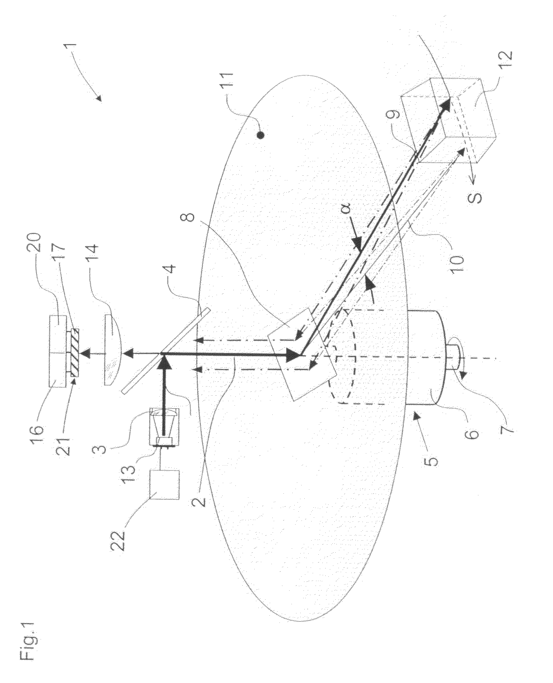
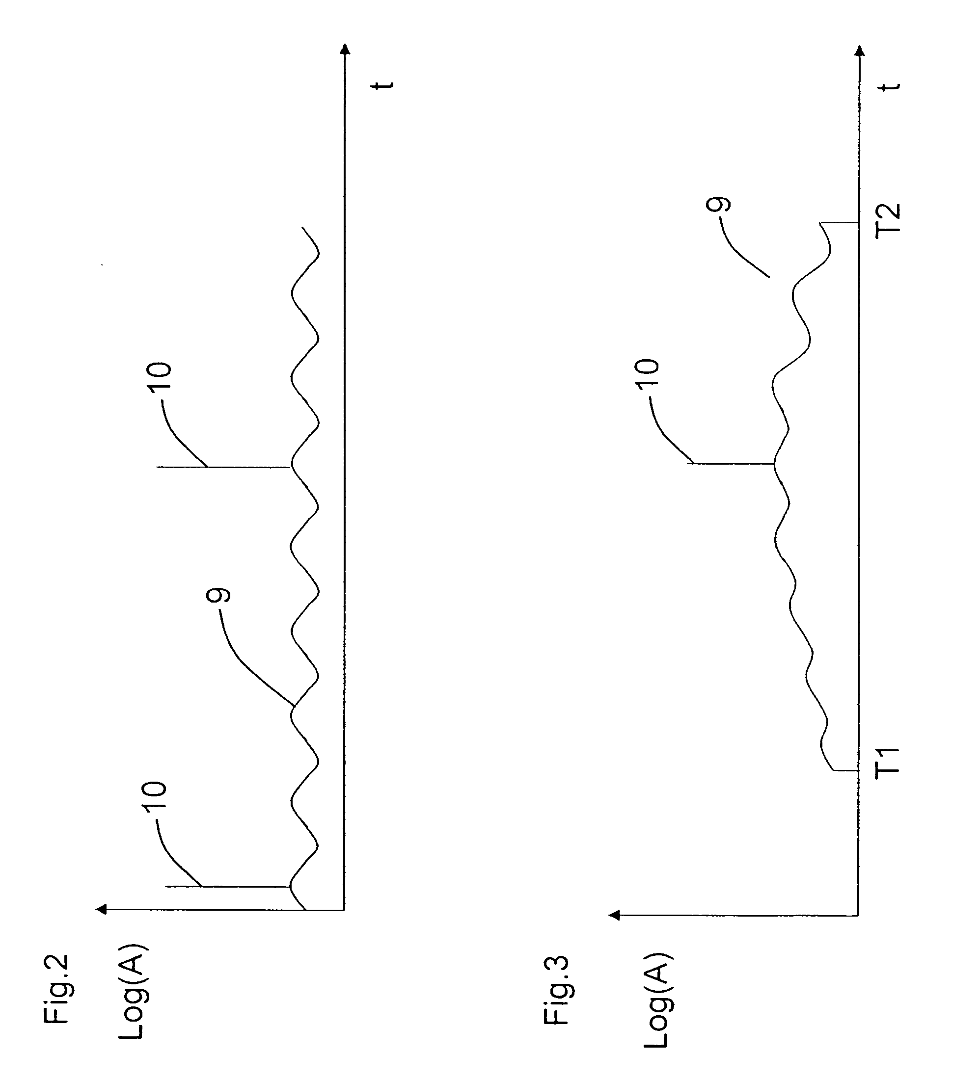
[0034]In the following the invention is described with reference to the embodiment of the invention shown in the drawings. FIG. 1 is a schematic, perspective view of a laser scanner 1 that emits light pulses 10 and a light measuring signal 9.

[0035]Such laser scanners are generally known from German patent publication DE 43 40 756 A1, the contents of which are incorporated herein by reference. This laser scanner operates on the basis of the elapsed time taken by the light; that is, successive light pulses are directed into a monitored region via a rotating mirror at a continuously changing angle. Pursuant to principles of autocollimation, received light pulses are evaluated on the basis of the elapsed time between the emission and receipt of light pulses while taking the speed of light into account. A distant signal is thereby generated which is representative of the distance between the laser scanner and an object. With the known angle of the rotating mirror, the position of the obj...


PUM


Abstract

A laser scanner which operates pursuant to the elapsed time principle and which has a pulsed laser that directs successive light pulses into a monitored region. The laser scanner further has a light receiving arrangement for receiving light pulses reflected by an object in the monitored region and that generates electric received signals which are fed to an evaluation unit for determining a distance between the object and the laser scanner based on the elapsed time between the emission of the light pulse and the receipt of the reflected pulse and the speed of light from which a distance signal is formed that is representative of the distance between the object and the scanner. There is a light diverter unit between the pulsed laser and the monitored region which continuously directs light pulses along different directions into the monitored region. A light source is provided which emits a light measuring signal of reduced strength which is also continuously directed into the monitored region in continuously changing directions. The light receiving arrangement is configured to receive the light measuring signal reflected by the object in the monitored region and to generate a reflection signal that is representative of the reflection characteristics of the object. The light pulses and the receiving signals are changeable in dependency of the reflection signal.

Description

CROSS-REFERENCES TO RELATED APPLICATIONS[0001]This application claims the priority of German Application No. 102006060108.4, filed Dec. 20, 2006, the disclosure of which is incorporated herein by reference.BACKGROUND OF THE INVENTION[0002]This invention relates to a laser scanner in accordance with the preamble of claim 1.[0003]Such a laser scanner or laser radar device is known from DE 43 40 756 A1. In that laser radar device, a pulsed laser directs controlled, successive light pulses into a monitored region. A light receiving arrangement detects light pulses that are reflected by an object in the monitored region and generates corresponding electric signals which are fed to an evaluation unit. The evaluation unit determines the distance between the object and the laser radar device and generates a representative distance signal on the basis of the time interval between the emission and receipt of the light pulse on the basis of the speed of light. A light diverter is arranged betw...

Claims


Application Information

Patent Timeline
Patent Type & Authority Applications(United States)
IPC IPC(8): G01C3/08G01S17/10
CPCG01S7/484G01S7/4868G01S17/42G01S17/10G01S7/497
Inventor MACK, STEFANPASTOR, SEBASTIANPIERENKEMPER, HANS-WERNER
Owner SICK AG
Why Eureka
Try Eureka